
Semi‑Solid Injection Molding of AZ91D Magnesium Alloy for Lightweight EV E‑Drive Housings
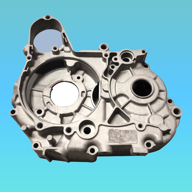
Driven by automotive lightweighting demands, semi‑solid injection molding of magnesium alloys stands out as a core near‑net‑shape solution for new‑energy electric drive systems. This work investigates the coupled effects of barrel temperature, screw speed and solid fraction. Through multi‑parameter collaborative optimization, we achieve a major performance upgrade for AZ91D e‑drive housings: tensile strength up 27% higher and elongation up 63% higher compared with conventional die casting.
Innovations including dual injection gates and a combined hot‑runner gating system successfully resolve filling difficulties for thin‑walled castings. We also established a 3D porosity quantification model based on XCT (X‑ray Computed Tomography), revealing the nonlinear relationship between screw recovery speed and the spheroidization of solid particles. These findings lay a solid foundation for large‑scale deployment of magnesium alloys in electric drive systems.
Magnesium alloy, with a density of only 1.74 g/cm³, is the lightest structural metal available. Its specific strength (tensile strength / density) reaches 1.5 times that of aluminum alloy and 2.3 times that of steel. However, severe dendrite segregation in traditional die casting commonly restricts the elongation of magnesium castings to below 4%, which prevents wider adoption in dynamically loaded e‑drive housings. Semi‑solid injection molding achieves shear‑induced primary phase spheroidization, producing grains smaller than 5 μm and breaking through classic casting performance limits. Most existing research focuses on slurry preparation for rheocasting, while standardized process specifications tailored for complex e‑drive housing structures remain scarce. Using AZ91D magnesium alloy as the test material, orthogonal process trials were carried out to build quantitative correlations between mechanical properties and key parameters: barrel temperature, injection speed and screw rotational speed.
Compared with conventional thixoforming, this process eliminates separate billet fabrication and re-heating. Spheroidization is realized directly via screw shearing. Magnesium pellets (1.2 mm × 1.2 mm × 4 mm) are subjected to electrical heating (580–630 °C) and screw shearing (100–165 rpm) inside the barrel. Primary α‑Mg dendrites break into spherical particles, and the solid fraction can be precisely tuned by temperature: approximately 26% at 580 °C, and nearly fully liquid at 630 °C. During injection, the melt is delivered at 3–5 m/s — roughly 10× the speed of standard plastic injection molding — enabling rapid filling of thin‑wall sections with an average wall thickness of 1 mm.
1. Gating System Design & Mold-Flow Simulation
The target magnesium e‑drive housing features overall dimensions of 566.8 mm × 384.3 mm × 384.3 mm, a minimum wall thickness of 3.5 mm and a blank weight of 6.7 kg. AZ91D magnesium pellets are processed on an Yizumi UN3200MGⅡ semi‑solid magnesium injection machine.

To accommodate its deep-cavity, thin-wall geometry, a symmetric dual‑gate plus hot‑runner layout was adopted. This design cuts the melt flow path by 30%. Hot runners are maintained at 600 °C ±5 °C to prevent premature solidification. Mold‑flow simulation confirms the fill time is reduced to 418.4 ms, with a 22% improvement in temperature‑field uniformity.
The two melt fronts advance simultaneously through hot nozzles toward the housing flange, converging in a V‑shape along the side walls. Simulated trapped gas concentrates near the root of top ribs. The thin‑wall zones stay at approximately 595 °C while thicker flanges sit near 590 °C, with a temperature difference below 5 °C. Fast filling prevents premature freezing in thin sections, while slightly lower temperatures in heavy sections reduce shrinkage porosity. The two streams merge at the top and form a fine knit line. The trapped gas volume is limited to merely 0.2 mm³, thanks to optimized vacuum venting and overflow runners.
2. Injection Process Parameter Development
Core process variables include forming temperature, screw speed and screw recovery speed. Raw magnesium pellets (1.2 mm × 1.2 mm × 4 mm) from Baowu Magnesium are heated and sheared inside the barrel to reach the semi‑solid state, then injected into a mold held at 200 °C. With screw speed fixed at 100 rpm and injection speed at 3 m/s, trials were performed across different injection temperatures. Too low injection temperature triggers knit lines and incomplete filling. In production, injection speed must be adjusted according to alloy grade and part geometry: higher speeds are generally required for thin walls, while slower injection suits thick sections. Excessively high flow velocity may also disrupt laminar filling and induce turbulence, pushing porosity upward.
2.1 Forming Temperature
Temperature control covers barrel zones, nozzle outlet temperature and mold temperature. Barrel and nozzle conditions determine slurry quality, while mold temperature governs filling behavior and cooling.
2.1.1 Barrel Temperature
Barrels consist of multiple independent heating zones for preheating, melting and holding. Solid fraction varies slightly for different magnesium alloys at identical temperatures, so barrel settings must be customized. Wall thickness and mold layout are also critical considerations. Thin‑wall cavities impose high flow resistance and short available cooling windows, requiring moderately higher barrel temperatures to preserve fluidity. For thick‑wall parts, barrel temperatures can be reduced. Complex geometries or long runners demand elevated injection speed for complete filling. Metallographic analysis of castings produced at 580 °C and 600 °C shows microstructures comparable to traditional magnesium die castings, mainly α‑Mg and intermetallic Mg₁₇Al₁₂, with minor dissolved Al and Zn. Barrel temperature shows limited impact on phase constitution, yet higher temperature improves fluidity and lowers solid fraction. The barrel temperature quoted herein refers specifically to the melting zone temperature, ensuring homogeneous semi‑solid slurry and minimizing gas entrapment. XRD analysis confirms the alloy consists primarily of α‑Mg matrix and β‑Mg₁₇Al₁₂ intermetallic phases.

2.1.2 Nozzle Temperature
Stable nozzle temperature is critical for consistent quality. Large temperature fluctuations cause knit lines, flash and sticking. Overheating triggers dripping; underheating raises discharge pressure, increases backflow and destabilizes shot metering. Tensile tests follow GB/T13822‑2017, performed on an electro‑hydraulic servo fatigue tester (LF5105) at a strain rate of 2.5 mm/min. Yield strength and elongation rise with injection temperature. The finest average grain size of 4 μm is achieved at 600 °C, making 600 °C ±5 °C the recommended injection window for this housing. XCT inspection reveals stark differences: over 20,000 pores at 640 °C and roughly 12,000 pores at 620 °C. Pores formed at 590 °C show high aspect ratios and a maximum pore volume of 21,064 μm³, severely degrading yield strength and ductility. Fracture surfaces display mixed brittle facets and ductile tear ridges, indicating a combined fracture mode. Porosity is governed not only by injection parameters but also by mold venting, vacuum setup and overflow design, requiring iterative tuning.

2.1.3 Mold Temperature
The temperature differential between semi‑solid slurry and mold strongly impacts forming. A large difference accelerates cooling and refines grains, yet for parts averaging only 1 mm in wall thickness, rapid solidification traps gas and creates pores. Low mold temperature also causes uneven cooling, warpage and cracking. Excessively high mold temperature slows cooling and coarsens grains. Typical mold temperature for this semi‑solid process ranges from 180 °C to 250 °C.
2.2 Screw Rotational Speed
High shear from the barrel screw controls primary dendrite refinement and spherical grain growth. Above a critical shear threshold, primary grains develop directly into spherical morphology. Higher agitation promotes spheroidization, reduces solid particle size and improves roundness. Screw speed must synchronize with feeder motion to guarantee accurate dosing. Under fixed conditions: injection speed 2 m/s, mold temperature 230 °C and barrel temperature 600 °C, tensile strength and elongation both improve as screw speed increases. At the maximum tested speed, tensile strength reaches 262 MPa (+21% vs conventional die‑cast AZ91D), and elongation hits 5.7% (+63%). Higher screw speed reduces solid fraction, boosting both strength and ductility.
2.3 Screw Recovery Speed
Recovery speed is a key thixomolding parameter controlling microstructure and performance. With injection speed, mold temperature, barrel temperature and packing ratio locked, trials demonstrate that lower recovery speed reduces shear rate, raises solid fraction and encourages particle agglomeration. Increased internal liquid phase reduces shrinkage and turbulence, lowering porosity. Conversely, higher recovery speed drives porosity upward.
2.4 Orthogonal Testing for Optimal Process
An orthogonal test matrix was designed for barrel temperature, screw speed and injection speed to evaluate responses in strength, elongation and porosity. At 600 °C and 165 rpm, α‑Mg particles achieve near‑spherical geometry with roundness >0.85, and eutectic Mg₁₇Al₁₂ is evenly dispersed. At 3.5 m/s injection speed, XCT records pore volume below 10,000 μm³ with smooth pore surfaces, greatly mitigating performance degradation from casting defects.
Nine repeated production runs were completed under the validated optimal window: barrel temperature 600 °C ±2 °C, screw speed 165 rpm ±5 rpm, injection speed 3.5 m/s ±0.2 m/s. Tensile strength fluctuates within only ±0.8 MPa. The coefficients of variation for elongation and porosity stay below 3%. Grain size stabilizes between 3.6 μm and 3.9 μm with spheroidization >0.85, proving reliable shear-field control.
A quantitative empirical formula relates ultimate tensile strength to barrel temperature, screw speed and solid fraction: σᵦ = 182 + 0.15T + 0.5n − 12fₛ Where σᵦ = ultimate tensile strength, T = barrel temperature, n = screw speed, fₛ = solid fraction.
The validated recipe supports stable mass production: cycle time fixed at 45 seconds per part with a production yield above 98%.
3. Key Conclusions
- Under the optimized window: injection temperature 600 °C ±5 °C, screw speed 165 rpm, injection speed 3.5 m/s, the AZ91D e‑drive housing achieves tensile strength of 261.7 MPa ±0.8 MPa and elongation of 5.7 ±0.15%, marking improvements of 27% and 63% over conventional die casting. High shear produces stable, fine α‑Mg grains (3.6–3.9 μm) and uniformly distributed eutectic Mg₁₇Al₁₂, the root cause of enhanced mechanical performance.
- Symmetric dual gates paired with a 600 °C hot runner shorten melt travel by 30% and deliver a fill time of 418.4 ms. Uniform temperature distribution eliminates incomplete filling and cold shut defects common in deep thin‑wall cavities. Our XCT 3D porosity model confirms a nonlinear correlation between recovery speed and particle spheroidization; porosity drops sharply when recovery speed falls below 140 rpm.
- The coupled interactions of barrel temperature, screw speed and solid fraction on component performance have been clarified, and the predictive strength model σᵦ = 182 + 0.15T + 0.5n − 12fₛ is established for process engineering.
Q: Mechanical performance vs standard die casting?
A: Our optimized AZ91D semi‑solid housing achieves 261.7 MPa tensile strength and 5.7% elongation, +27% strength and +63% elongation over conventional die casting, ideal for dynamic EV loads.
Q: Mass production stability, cycle time & yield?
A: Excellent repeatability: strength tolerance ±0.8 MPa, CV of elongation & porosity <3%. Stable cycle: 45 s/pc, yield>98%. XCT inspection ensures low porosity.
Q: Thin-wall capability & max part size?
A: Minimum wall 3.5 mm, suitable for avg 1 mm thin sections. Proven part size: 566.8 × 384.3 × 384.3 mm. Custom dimensions accepted upon drawing review.
Q: How do you control porosity, cold shuts and knit lines?
A: Symmetric dual-gate hot runner (600 ℃) shortens flow path by 30%, plus vacuum venting & overflow. XCT porosity monitoring suppresses gas defects and knit lines.
Q: Do you support custom motor housing & prototype runs?
A: Yes. We offer custom lightweight magnesium e‑drive housings, including prototype sampling, small-batch validation and mass production with tailored process parameters.
Common Defects of Die Cast Components & Preventive Solutions


For more questions please
contact us

+86 755 28280203


315 PING 'AN AVENUE, PINGHU STREET, LONGGANG DISTRICT, SHENZHEN CITY, GUANGDONG PROVINCE