Research On Graphite-ceramic Composite Casting Technology Of An Aerospace Titanium Alloy Shell Casting
Research on graphite-ceramic composite casting technology of an aerospace titanium alloy shell casting
Guided reading
In view of the high requirements on the surface quality of the runner for the titanium alloy shell casting, the graphite-ceramic composite mold is selected to ensure the surface quality of the runner of the casting. Improve the internal quality of castings, and combine software calculation and theoretical analysis to clarify the mechanism of ceramic materials to improve the surface quality of casting runners.
Titanium and titanium alloys have a series of excellent properties such as high specific strength, high temperature resistance and corrosion resistance, and are called "space metals" and "marine metals". In order to further expand its application range, on the basis of ordinary alloys, by reducing the content of interstitial elements, ELI (extra low interstitial, ultra-low interstitial, ultra-low interstitial) titanium alloys are obtained. The toughness is significantly improved while the strength is reduced, which is widely used. It is widely used in important fields such as cryogenic engineering, medical treatment, marine engineering and so on.
TC4ELI titanium alloy is obtained by controlling the content of interstitial elements C, N, O and impurity element Fe on the basis of TC4 alloy. Figure 1 shows a titanium alloy shell casting, a key component used at low temperature in a commercial aerospace equipment. The material is ZTC4ELI titanium alloy. The flow channel of the casting has a hydrodynamic profile. In order to ensure the design performance of the shell, the surface quality is very high. Due to structural limitations, the near-net shape can only be achieved by the casting method. At the same time, surface defects should be avoided. Defects cannot be repaired. By adopting the graphite-ceramic composite process, the shell castings with internal quality, surface quality, dimensional accuracy and physical and chemical properties all meet the requirements.

The outline size of the titanium alloy shell casting is 585mm × 386mm × 291mm, the flow channel is irregular and variable section, the basic wall thickness is only 4mm, and the surface roughness of the flow channel is not more than 3.2 μm. Combined with the structural characteristics, the process adopts two types: fusion model and machine-added graphite type. Investment casting requires the preparation of metal molds and water-soluble cores respectively. Although the surface roughness of the runner can be guaranteed, the dimensional accuracy of the wax mold is difficult to guarantee. And there is no advantage in the cycle. The machined graphite type process uses electrode graphite material, which is assembled into a mold by machining. The surface is prone to defects such as cold insulation, flow marks and cracks, which seriously affect the surface quality of the casting runner. In response to this problem, graphite-ceramic composite casting is used, electrode graphite is used for the outer mold, and ceramic material is used for the inner core. Compared with graphite, the difficulty of cleaning the mold after pouring is greatly reduced, which is conducive to ensuring the surface quality of the runner.
1
Pouring process design and mold preparation
According to the structural characteristics of the casting, the gating system adopts the bottom injection type, and the complete filling of the casting is realized through the evenly distributed ribs. The casting simulation software was used to simulate the gating system, and it was found that there were shrinkage holes, which were mainly concentrated on the end face of the outlet flange, the end face of the upper flange, and the middle flange, as shown in Figure 2. Due to the limitation of the structure of the casting itself, the casting has a narrow section and a thick section area during the filling process, which leads to the formation of an independent hot spot in the thick and large flange area of the casting, which is easy to form shrinkage holes.

Fig. 2 The position of the shrinkage cavity in the casting before optimization
In view of the above situation, the gating system is optimized, a riser is set at the outlet flange, and process ribs are added to form a more stable casting structure, which can improve the filling quality and reduce the deformation tendency of the outlet flange; from the casting , In terms of the structure of the middle flange, the shrinkage hole of the middle flange is an independent hot joint area. Even if a riser is set at the upper flange, the problem of shrinkage hole at the middle flange cannot be completely solved, so it is necessary to add a feeding channel. The riser at the upper flange can feed the middle flange, and at the same time, a filling channel is added near the gate, so that the molten metal can be filled quickly. See Figure 3. The feeding channel and the filling channel are hot. After pressing, it is removed by machining. The optimized gating system is shown in Figure 4.

Figure 3 Schematic diagram of casting filling and feeding channels

Figure 4 Shell casting gating system
The optimized gating system was simulated again, and the boundary conditions were the same as before optimization. It was found that the shrinkage cavity defects in the above three places were completely concentrated at the riser, and the shrinkage cavity defects in the casting were eliminated, as shown in Figure 5.

Fig. 5 Shrinkage hole position of casting after optimization
2
Mold design and preparation
The overall mold is in the form of left and right parting, as shown in Figure 6. The left and right outer molds are machine-added graphite type, the middle core is ceramic type, the ceramic core and the graphite type are gap fit, the matching accuracy is 0~0.05mm, the graphite type adopts positioning pins, heat-resistant steel Screws and other materials are used for assembly and positioning to ensure dimensional accuracy.

(a) Left outer mold (b) Right outer mold + ceramic core
Figure 6 Mold design model
The surface layer of the ceramic core is made of oxide material Y2O3. The Y2O3 ceramic material shell has good inertness and hardly reacts with the titanium alloy melt with high activity, which can reduce the thickness of the α sticky layer on the surface of the casting, and can reduce the thickness of the α-fouling layer on the casting surface. To maximize the surface quality of the casting, the ceramic core is shown in Figure 7.

Figure 7 Ceramic core
3
Scheme verification
3.1 Melting and pouring
After the mold assembly is completed, the overall preheating is carried out according to the process. The preheating temperature is 350±50℃, and the temperature is kept for more than 2 hours to ensure that the mold is fully preheated, improve the filling ability of the molten metal, and reduce the cold insulation, flow marks and cracks of the casting. and other surface defects. The poured casting is shown in Figure 8. It can be seen that the surface of the casting has a metallic luster, and the forming quality is good, as expected.

Figure 8 Shell casting (after cleaning)
3.2 Quality inspection
After the casting has been hot isostatic pressing, there is no large-scale shrinkage hole defect at the flange. The optimized pouring scheme meets expectations, effectively reducing casting defects and improving casting quality. There is no excess fluorescence defect in the casting runner. Compared with the roughness samples, the surface roughness Ra in the flow channel is less than or equal to 3.2μm, which meets the technical requirements. In order to further analyze the influence of graphite materials and ceramic materials on the surface quality of castings, 6 points were randomly selected on the surface where the molten metal contacts the inner core of the casting mold, and the positions are shown in Figure 9. Using the software, the curves of the cooling rate of the molten metal when using graphite materials and ceramic materials were calculated, respectively, as shown in Figure 10.

Figure 9 Schematic diagram of point selection location
It can be seen from Figure 10 that when graphite and ceramic are used as the mold shells, the cooling rate of the molten metal is faster at the moment when the casting is completed, and then the solidification rate of the graphite shell casting is significantly faster than that of the ceramic shell casting. 20s after the completion, the temperatures of the two molten metals were above 1100 °C and above 1250 °C, respectively. The main reason is that the thermal conductivity of graphite materials is significantly higher than that of ceramic materials, resulting in different solidification rates of molten metal, which is also the key factor for the difference in surface quality. . At the same time, it is found in the curve that the solidification rate of point 6 near the runner is significantly slower than that of other positions due to the continuous overheating of the molten metal.
(a) Graphite material
(b) Ceramic materials

Fig.10 Influence curve of graphite material and ceramic material on the cooling rate of molten metal
The main reason why the surface quality of ceramic mold castings is better than that of graphite molds is that during the flow of molten metal, the front end of the casting mold is cooled and solidified. The solidified layer is remelted by the subsequent superheated metal, as shown in Figure 11, resulting in fewer surface defects such as flow marks and cold insulation, and a lower surface roughness value. The surface quality in the flow channel is shown in Figure 12.

Figure 11 Schematic diagram of molten metal filling and cooling process

Figure 12 Surface quality of casing casting runner
3.3 Size detection
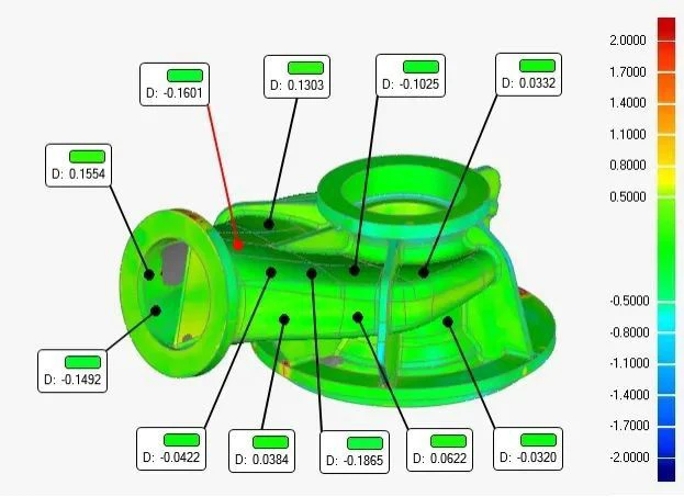
Dimensional and shape inspection of castings was carried out using three-dimensional laser scanning equipment (HandySCAN700). The results are shown in Figure 13. It can be seen from the comparison results that the casting is in good agreement with the theoretical model 3D, and the deviation between the non-machined parts such as the runner and the theoretical model is within the tolerance of ±0.2mm, which fully meets the requirements.

Figure 13 3D scanning comparison results of castings
3.4 Physical and chemical performance testing
The physical and chemical properties of the castings were tested by taking the attached casting samples in the state of hot isostatic pressing and annealing. The technical indicators and measured data are shown in Table 1 and Table 2. The measured data fully meet the requirements of the technical indicators.


4
in conclusion
The use of graphite-ceramic composite casting molds to produce titanium alloy shell castings can effectively reduce the surface cold insulation, flow marks, cracks and other defects of the flow channel, and ensure the surface quality of the non-processing area of the product. With the help of casting simulation software, the location of defects such as shrinkage holes can be accurately identified. By optimizing the design of the gating system, increasing the filling, feeding channels and risers, the internal defects of the casting can be effectively reduced. Through software calculation and theoretical analysis, the ceramic mold shell with lower thermal conductivity can effectively ensure the surface quality of the casting compared with the graphite mold shell.
Citation format: Zhang Yang, Liang Runzi, Yu Zongming, et al. Research on graphite-ceramic composite casting technology for titanium alloy shell castings [J]. Special Casting and Nonferrous Alloys 2021,41(12):1 572-1 575.
Nine Major Errors in Machining, How Many Do You Know?
Professor Yang Xiangjie Of Nanchang University: A New Method For The Preparation Of AZ91D Magnesium Alloy Semi-solid Slurry
Related Article