Analysis of Difficulties in Stainless Steel Material Processing
Author: SZTC
2024-05-06
The difficulties in processing stainless steel materials mainly include the following aspects:
1. High cutting force and high cutting temperature
This type of material has high strength, large tangential stress and large plastic deformation during cutting, so the cutting force is large. In addition, the thermal conductivity of the material is extremely poor, causing the cutting temperature to rise, and the high temperature is often concentrated in the narrow area near the cutting edge of the tool, thus accelerating the wear of the tool.
2. Severe work hardening
Austenitic stainless steel and some high-temperature alloy stainless steels have an austenitic structure and have a large tendency to work harden during cutting, usually several times that of ordinary carbon steel. The tool cuts in the work-hardened area, shortening the tool life.
3. Easy to stick to the knife
Both austenitic stainless steel and martensitic stainless steel have the characteristics of strong chips and high cutting temperature during processing. When strong chips flow through the rake face, adhesion, welding and other sticking phenomena will occur, affecting the surface roughness of the machined parts.
4. Accelerated tool wear
The above-mentioned materials generally contain high-melting-point elements, have high plasticity, and have high cutting temperatures, which accelerate tool wear and require frequent tool sharpening and tool replacement, thus affecting production efficiency and increasing tool usage costs.
The main purpose is to reduce the cutting line speed and feed. Use tools specially designed to process stainless steel or high-temperature alloys, and it is best to use internal cooling for drilling and tapping.
Stainless steel parts processing technology
Through the above analysis of processing difficulties, the processing technology and related tool parameter design of stainless steel should be quite different from ordinary structural steel materials. The specific processing technology is as follows:
1.Drilling processing
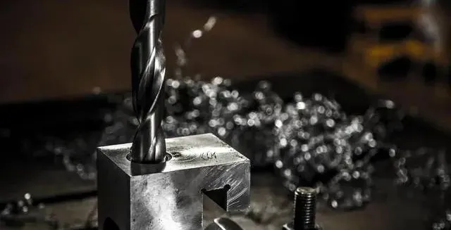
During drilling processing, due to the poor thermal conductivity and small elastic modulus of stainless steel materials, it is also difficult to process holes. To solve the problem of hole processing in such materials, it is mainly to select appropriate tool materials, determine reasonable geometric parameters of the tool, and the cutting amount of the tool. When drilling the above materials, drill bits should generally use drill bits made of W6Mo5Cr4V2Al, W2Mo9Cr4Co8 and other materials. The disadvantages of drill bits made of these materials are that they are relatively expensive and difficult to purchase. When drilling with the commonly used W18Cr4V ordinary standard high-speed steel drill bit, there are shortcomings such as the small vertex angle, the chip is too wide to be discharged out of the hole in time, and the cutting fluid cannot cool the drill bit in time. In addition, the stainless steel material has poor thermal conductivity, causing concentration. The cutting temperature on the cutting edge increases, which can easily cause burns and chipping of the two flank surfaces and the main edge, reducing the service life of the drill bit.
1) Tool geometric parameter design When drilling with W18Cr4V ordinary high-speed steel drill bit, the cutting force and cutting temperature are concentrated on the drill tip. In order to improve the durability of the cutting part of the drill bit, the vertex angle can be appropriately increased. The vertex angle is generally selected 135°~140°. The increase in the vertex angle will also reduce the outer edge rake angle and narrow the drilling chips to facilitate chip removal. However, after increasing the vertex angle, the chisel edge of the drill bit becomes wider, resulting in increased cutting resistance. Therefore, the chisel edge of the drill bit must be ground. After grinding, the bevel angle of the chisel edge is 47° to 55°, and the rake angle of the chisel edge is 3°~5°. When grinding the chisel edge, the corner between the cutting edge and the cylindrical surface should be rounded to increase the strength of the chisel edge. Since the elastic modulus of stainless steel materials is small, the elastic recovery of the metal under the chip layer is large, and the work hardening is severe during processing. If the clearance angle is too small, the wear of the drill bit flank surface will be accelerated, the cutting temperature will be increased, and the life of the drill bit will be reduced. Therefore, the relief angle must be appropriately increased. However, if the relief angle is too large, the main edge of the drill will become thin and the rigidity of the main edge will be reduced. Therefore, the relief angle should be 12° to 15°. In order to narrow the drill chips and facilitate chip removal, it is also necessary to open staggered chip grooves on the two flank surfaces of the drill bit.
2) When selecting cutting amount for drilling, the selection of cutting amount should start from the basic point of reducing the cutting temperature, because high-speed cutting will increase the cutting temperature, and high cutting temperature will aggravate tool wear, so the cutting amount is the most important is to select the cutting speed. Generally speaking, the cutting speed is 12-15m/min. The feed rate has little effect on the tool life, but if the feed rate is too small, the tool will cut in the hardened layer, aggravating wear; if the feed rate is too large, the surface roughness will deteriorate. Based on the above two factors, it is appropriate to choose the feed amount between 0.32 and 0.50mm/r.
3) Cutting fluid selection: In order to reduce the cutting temperature during drilling, emulsion can be used as the cooling medium.
2. Reaming processing
1) Tool geometric parameter design Most of the reaming processing of stainless steel materials uses carbide reamers. The structure and geometric parameters of the reamer are different from ordinary reamers. In order to enhance the strength of the cutter teeth and prevent chip clogging during reaming, the number of reamer teeth is generally relatively small. The rake angle of the reamer is generally 8° to 12°, but in some specific cases, in order to achieve high-speed reaming, a rake angle of 0° to 5° can also be used; the relief angle is generally 8° to 12°; the main deflection angle is The selection depends on the hole. Generally, the through hole is 15°~30°, and the closed hole is 45°. In order to discharge the chips forward when reaming, the blade inclination angle can also be appropriately increased. The blade inclination angle is generally 10 °~20°; the blade width is 0.1~0.15mm; the inverted taper on the reamer should be larger than that of ordinary reamers. Carbide reamers are generally 0.25~0.5mm/100mm, and high-speed steel reamers are 0.1~0.25mm/ 100mm; the length of the correction part of the reamer is generally 65% to 80% of that of an ordinary reamer, and the length of the cylindrical part is 40% to 50% of that of an ordinary reamer.
2) Selection of cutting amount: When reaming, the feed amount is 0.08~0.4mm/r, the cutting speed is 10~20m/min, the rough reaming allowance is generally 0.2~0.3mm, and the fine reaming allowance is 0.1~0.2mm. Carbide tools should be used for rough reaming, and high-speed steel tools can be used for fine reaming.
3) Cutting fluid selection: When reaming stainless steel materials, total loss system oil or molybdenum disulfide can be used as the cooling medium.
3. Boring processing
1) Tool material selection: Due to the high cutting force and high cutting temperature when processing stainless steel parts, the tool material should try to choose YW or YG carbide with high strength and good thermal conductivity. YT14 and YT15 carbide inserts can also be used for finishing. When processing parts made of the above materials in batches, ceramic material tools can be used. Since this type of material is mainly characterized by high toughness and severe work hardening, the chips produced when cutting these materials are generated in the form of unit chips, which will cause the tool to vibrate and easily cause microscopic vibrations on the blade. Therefore, when choosing ceramic tools to cut parts made of such materials, the first thing to consider is microscopic toughness. At present, Sialon is a better choice, especially α/βSialon material, which is eye-catching due to its excellent resistance to high temperature deformation and diffusion wear. It has been successfully used in cutting nickel-based alloys, and its service life far exceeds Al2O3 based ceramics. In addition, SiC whisker-reinforced ceramics are also a very effective tool material for cutting stainless steel or nickel-based alloys.
For the processing of quenched parts made of such materials, CBN (cubic boron nitride) blades can be used. The hardness of CBN is second only to diamond, and the hardness can reach 7000~8000HV. Therefore, it has high wear resistance. Compared with diamond, the outstanding advantages of CBN are The heat resistance is much higher than diamond, reaching 1200°C, and can withstand high cutting temperatures. In addition, it is very chemically inert and does not interact chemically with iron group metals at 1200 to 1300°C, so it is very suitable for processing stainless steel materials. Its tool life is dozens of times that of carbide or ceramic tools.
2) Design of tool geometric parameters. Tool geometric parameters play an important role in its cutting performance. In order to make cutting light and smooth, carbide tools should use a larger rake angle to increase tool life. Generally, the rake angle is 10° to 20° during rough machining, 15° to 20° during semi-finishing, and 20° to 30° during finishing. The basis for selecting the main deflection angle is that when the process system has good rigidity, it can be 30° to 45°; if the process system has poor rigidity, it can be 60 to 75°. When the ratio of the length to diameter of the workpiece exceeds 10 times, it can be 90 °.
When boring stainless steel materials with ceramic tools, in most cases, the ceramic tools use a negative rake angle for cutting. The rake angle size should generally be -5°~-12°. This will help strengthen the blade and give full play to the advantages of high compressive strength of ceramic tools. The size of the relief angle directly affects the tool wear and also affects the strength of the blade. Generally, 5°~12° is selected. Changes in the main deflection angle will affect the changes in the radial cutting component force and the axial cutting component force as well as the cutting width and cutting thickness. Because the vibration of the process system is extremely detrimental to ceramic cutting tools, the selection of the main deflection angle should be conducive to reducing this vibration, generally 30° to 75°. When CBN is selected as the tool material, the tool geometric parameters are rake angle 0°~10°, relief angle 12°~20°, and main deflection angle 45°~90°.
3) The roughness value should be small when sharpening the rake surface. In order to avoid the phenomenon of chips sticking to the tool, the front and rear surfaces of the tool should be carefully ground to ensure a small roughness value, thereby reducing the resistance to chip outflow and avoiding chipping. Sticky knife.
4) The cutting edge of the tool should be kept sharp to reduce work hardening. The feed amount and the amount of back cutting should not be too small to prevent the tool from cutting in the hardened layer and affecting the service life of the tool.
5) Pay attention to the grinding of the chip breaker. Since stainless steel chips have strong and tough characteristics, the chip breaker on the rake surface of the tool should be properly ground, so that chip breaking, chip holding and chip removal are convenient during the cutting process.
6) Selection of cutting amount. According to the characteristics of stainless steel materials, it is advisable to use low speed and large feed amount for cutting.
When using ceramic tools for boring, the reasonable selection of cutting amount is one of the keys to giving full play to the performance of ceramic tools. When cutting ceramic tools continuously, the cutting amount can be selected according to the relationship between wear durability and cutting amount; for intermittent cutting, the reasonable cutting amount should be determined according to the tool breakage pattern. Since ceramic tools have superior heat resistance and wear resistance, the impact of cutting amount on tool wear life is smaller than that of carbide tools. In general, when processing with ceramic tools, the feed rate is the most sensitive to tool breakage. Therefore, according to the nature of the workpiece material, and subject to the permission of the machine tool power, process system stiffness and blade strength, when boring stainless steel parts, try to choose a high cutting speed, a large back cutting amount and a relatively small advance. Give amount.
7) The selection of cutting fluid must be appropriate. Since stainless steel is prone to bonding and has poor heat dissipation, it is very important to choose a cutting fluid with good bonding resistance and heat dissipation during boring. For example, use a cutting fluid with a high chlorine content. As well as mineral oil-free, nitrate-free aqueous solutions with good cooling, cleaning, anti-rust and lubricating effects, such as H1L-2 synthetic cutting fluid.
Using the above process method can overcome the difficulties of stainless steel processing, greatly improve the tool life when drilling, reaming, and boring stainless steel, reduce the number of tool sharpening and tool changes during operation, and improve production efficiency and hole processing quality. Satisfactory results can be achieved in reducing workers' labor intensity and production costs.
Microstructure and mechanical properties of semi-solid modified 6061 aluminum alloy rheological die-casting specimens
The Difference Between High Speed Steel And Tungsten Steel
Related Article
Fast sampling is the fastest way to win business in the hardware machining and plastic mold industries. Customers want a working sample in days, and a 3D printer delivers it, but only when you know how to print in 3d correctly.
how to print in 3d
Fast sampling is the fastest way to win business in the hardware machining and plastic mold industries. Customers often send an STL file and expect a working sample in days.
how to print an stl file