Improvement Of Aluminum Alloy Clutch Housing Leakage Problem
Author: ZZXY
2024-08-24
Die casting, short for pressure casting, is a precision molding process for metal parts close to the final shape and size; the die casting process has the advantages of good product quality, high dimensional accuracy, high production efficiency, and excellent economic effect. Therefore, it is widely used in machinery, automobiles, aerospace, electronics and other fields, and has broad prospects. Among them, die castings in the automotive field account for the highest proportion, about 50%. The strong domestic and foreign demand of the automobile industry has greatly promoted the rapid development of aluminum alloy die castings. At the same time, the advantages of aluminum alloy die castings, such as lightweight, high strength and low cost, have further promoted the development of the automobile industry. The two complement each other, making more and more parts adopt die casting process molding, so the product structure tends to be complicated, and the technical requirements for die casting process are also improved.
Taking the engine block, cylinder head, gearbox clutch housing, and shell cover as an example, there are multiple oil circuits inside the product, and the large cavity is soaked in oil for a long time. The pressure in the cavity during the working process of the engine and gearbox is extremely high, and leakage problems will occur if there is a slight defect. Therefore, the sealing requirements for the aluminum alloy die casting housing are extremely high. Considering the characteristics of die-casting process, shrinkage and porosity inside castings cannot be completely avoided. It is necessary to further improve the quality of castings and reduce defects through means such as product structure, mold design, and die-casting production process adjustment.
The main reason for product leakage is that the shrinkage, shrinkage, cracks and other defects inside the product penetrate the inner and outer walls of the product. The following takes the clutch housing in the transmission as an example to introduce various defect improvement solutions to improve product quality, increase product yield, and reduce production costs.
The common risk points of the oil channel in the early stage of design can basically be identified, so they are omitted here.
1. Identification of product leakage problems
The gearbox cavity is lubricating grease. Considering that the gas molecules are only 1/7-1/3 of the volume of the oil molecules, the large cavity of the product can be filled with air, and the gas leakage can be detected to identify whether the product is leaking; because the specific location needs to be known to improve the defect, the product is placed inside the water tank. The water inspection of the product leakage point is the preferred solution. After identifying the leakage point, the next step of improvement can be carried out.
The gearbox cavity is lubricating grease. Considering that the gas molecules are only 1/7-1/3 of the volume of the oil molecules, the large cavity of the product can be filled with air, and the gas leakage can be detected to identify whether the product is leaking; because the specific location needs to be known to improve the defect, the product is placed inside the water tank. The water inspection of the product leakage point is the preferred solution. After identifying the leakage point, the next step of improvement can be carried out.
2. Leakage improvement case
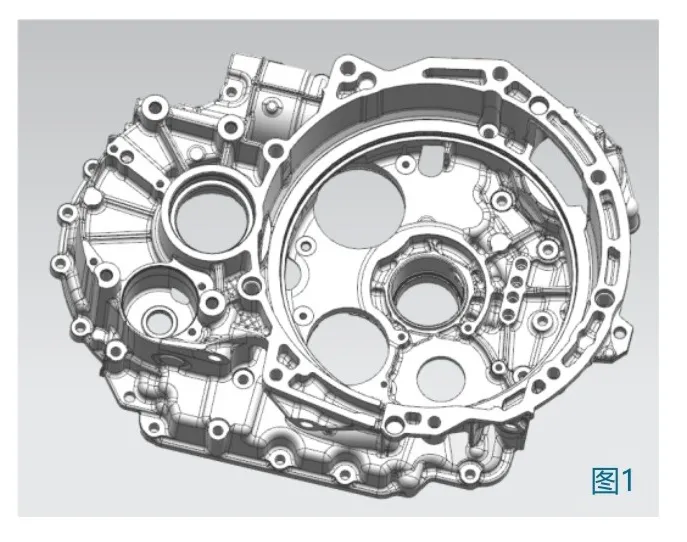
Figure 1 is a casting of a clutch housing for automobiles. The product has an overall dimension of 503mm*373mm*184mm, a product weight of 9kg, a basic wall thickness of 4m, and is manufactured using a 2500T die-casting machine.
Figure 1 is a casting of a clutch housing for automobiles. The product has an overall dimension of 503mm*373mm*184mm, a product weight of 9kg, a basic wall thickness of 4m, and is manufactured using a 2500T die-casting machine.

2.1. Introduction to improvement of leakage point 1

As shown in Figures 2 and 3 above, the water inspection results show obvious bubbles. Combined with Figures 4 and 5, it can be seen that there are shrinkage holes inside the product, and the surface of the product is sticky, which causes the dense layer to be destroyed. The two combined factors lead to leakage problems in the product. For the above problems, we can solve the internal shrinkage holes and the surface sticky mold to improve the leakage problem to the greatest extent.
2.1.1 Analysis of the causes of shrinkage holes
This is the weight reduction groove area. Combined with the product wall thickness analysis in Figure 6 and the solidification simulation analysis in Figure 7, it can be seen that the wall thickness of the product bearing hole position is too large. During the solidification process of the product, the shrinkage channel is closed, and the area marked by the red box cannot be replenished with aluminum liquid in time, resulting in shrinkage holes in the product.
This is the weight reduction groove area. Combined with the product wall thickness analysis in Figure 6 and the solidification simulation analysis in Figure 7, it can be seen that the wall thickness of the product bearing hole position is too large. During the solidification process of the product, the shrinkage channel is closed, and the area marked by the red box cannot be replenished with aluminum liquid in time, resulting in shrinkage holes in the product.
Shrinkage hole improvement plan: From the above analysis of the causes, it can be seen that shrinkage holes are caused by uneven solidification sequence of aluminum liquid and no aluminum liquid shrinkage at the last solidification position. Therefore, the improvement of this position can be started by changing the solidification sequence of aluminum liquid, adding cold water, adjusting the surface problems of the mold, forming sequential solidification, and improving the internal shrinkage hole defects of the product.

Since the minimum position of this weight reduction groove is only 11mm, the general point water cannot meet the addition requirements. It is necessary to add D4 high-pressure point cold water here (as shown in Figure 8). At this time, the minimum wall thickness of the mold on one side is only 3.5mm. In order to avoid the impact of subsequent cracking problems on production, this place is simultaneously modified to an insert for easy replacement after cracking.
After adding high-pressure cooling water to the mold, it is necessary to cooperate with the high-pressure spot cooling machine to accurately control the cooling opening and closing time. The mold here is small in size, so the heat obtained by the mold from the aluminum liquid is small. According to the law of conservation of energy, the heat that the mold needs to transfer from the cooling system is also small, so the high-pressure spot cooling water does not need to be turned on for a long time, otherwise it will cause the mold surface temperature to be too low, and there will be a risk of cold material; the usual solution is to turn on the high-pressure spot cooling water after the aluminum liquid enters the cavity, and the cooling ends after the product is demolded. With the high-pressure spot cooling machine that can independently control the spot cooling water channel (as shown in Figure 9), the cooling time and flow rate are accurately controlled to improve the stability of the production process and avoid shrinkage problems, thereby achieving the purpose of improving leakage. Combined with the local water quality, it is recommended to equip the area with poor water quality with a pure water machine, otherwise there will be scale blocking the high-pressure spot cooling pipe (as shown in Figure 10), resulting in the failure of the high-pressure spot cooling water and the recurrence of product shrinkage.

Improvement effect of high-pressure spot cooling water: After adding high-pressure spot cooling water, the product section is X-ray inspected. As shown in Figure 11, there is no shrinkage problem inside.

2.1.2 Causes of sticking
As shown in Figure 12, the common failure modes of die casting molds are: ①, aluminum solution adheres to the mold surface to cause material deposition; ②, aluminum solution reacts chemically with the mold substrate to produce Fe-Al-Si compounds attached to the mold surface; ③, thermal cracks appear during repeated heating and cooling; ④, erosion of the mold surface caused by the high-speed flow channel of aluminum liquid. The sticking of the weight loss groove of this product is mainly caused by ① and ④. The sticking of aluminum on the mold surface causes the mold temperature to be too high and the product surface is burned; at the same time, the mold surface is no longer smooth. Combined factors cause the dense layer on the product surface to be destroyed, and the two sides of the blank surface are connected through the central shrinkage hole, causing the product to leak from the inside out.
As shown in Figure 12, the common failure modes of die casting molds are: ①, aluminum solution adheres to the mold surface to cause material deposition; ②, aluminum solution reacts chemically with the mold substrate to produce Fe-Al-Si compounds attached to the mold surface; ③, thermal cracks appear during repeated heating and cooling; ④, erosion of the mold surface caused by the high-speed flow channel of aluminum liquid. The sticking of the weight loss groove of this product is mainly caused by ① and ④. The sticking of aluminum on the mold surface causes the mold temperature to be too high and the product surface is burned; at the same time, the mold surface is no longer smooth. Combined factors cause the dense layer on the product surface to be destroyed, and the two sides of the blank surface are connected through the central shrinkage hole, causing the product to leak from the inside out.
Improvement of mold sticking problem: From the above analysis, it can be seen that mold sticking is mainly caused by the damage of the mold surface, the appearance of other impurities, and excessive roughness. The solution is to use physical vapor deposition technology to deposit two or more layers of ceramic nitride coatings of different compositions (PVD coatings for short) on the mold surface. This coating has good chemical inertness and does not react with aluminum water, thereby blocking the direct contact between Al and Fe (as shown in Figure 13). It is applied to aluminum die-casting molds, which can greatly improve the erosion and wear resistance of the workpiece and avoid mold sticking problems. Considering the cost problem, the leakage position has been changed from the mold body to the insert, and the insert has been added with PVD coating. The mold sticking problem of the product has been improved, and there is no burning problem on the product surface.

2.1.3 Improvement result description
After adding high-pressure point cooling water and insert PVD coating, the leakage rate here has dropped from the original leakage rate of about 1.3% to less than 0.1%. If there is no problem with high-pressure point cooling water, there will be no leakage problem.
After adding high-pressure point cooling water and insert PVD coating, the leakage rate here has dropped from the original leakage rate of about 1.3% to less than 0.1%. If there is no problem with high-pressure point cooling water, there will be no leakage problem.
2.2 Leakage point 2 improvement introduction
As shown in Figures 14 and 15, both marked holes have leakage problems, and large shrinkage holes can be seen at the bottom of the two holes; the specifications of the two holes are M10, depth 40mm; M12, depth 58mm; both holes are processed holes, and there is no dense layer on the blank surface. Solving the leakage problem mainly starts from improving the shrinkage problem.
As shown in Figures 14 and 15, both marked holes have leakage problems, and large shrinkage holes can be seen at the bottom of the two holes; the specifications of the two holes are M10, depth 40mm; M12, depth 58mm; both holes are processed holes, and there is no dense layer on the blank surface. Solving the leakage problem mainly starts from improving the shrinkage problem.
Analysis of shrinkage causes: The depth of the two holes is deep. Under the condition of 1.5° draft, the processing allowance of the bottom of the hole is more than 2mm on one side, the wall thickness of the product is increased, and the heat junction is serious (the heat junction area in Figure 16 is extremely large). When the product solidifies, shrinkage holes are generated inside the product. After processing, the shrinkage holes leak out, and the leakage channel of the product cavity is opened through this shrinkage hole, causing leakage problems.
Shrinkage improvement plan: Since the heat junction here is large and the precast hole is small, the heat taken away by the high-pressure spot cooling is less than the heat released by the solidification shrinkage here, and the shrinkage hole will still exist; so it is more appropriate to use a local pressurization plan here. The two holes are deep and different in depth, and the shrinkage holes are concentrated at the bottom of the holes. Traditional extrusion cannot meet the requirements. As shown in Figure 17, a precast pin needs to be added to the end of the extrusion pin to ensure that the extrusion stroke can be extruded to the bottom of the hole to complete the shrinkage compensation; as shown in Figure 19, after the extrusion is added, there is no shrinkage problem at the bottom of the threaded hole, and there is no risk of leakage. In order to avoid the bending problem of the extrusion pin due to excessive length, the surface of the extrusion pin needs to be coated with PVD to improve the erosion resistance of the extrusion pin and delay the occurrence of thermal cracks, improve production efficiency, and avoid frequent replacement of extrusion.

Improvement result description: After adding double extrusion, the leakage rate here is reduced from the original leakage rate of about 2% to less than 0.2%, and there will be no leakage problem when there is no failure problem in extrusion.
3. Practical technology sharing of double extrusion
3.1. Introduction to double extrusion structure
As shown in Figure 20 above, the double extrusion is mainly composed of extrusion pin, extrusion pin sleeve, fixed block, and extrusion cylinder.
3.1. Introduction to double extrusion structure
As shown in Figure 20 above, the double extrusion is mainly composed of extrusion pin, extrusion pin sleeve, fixed block, and extrusion cylinder.
3.2. Calculation of double extrusion pressure
The extrusion pressure depends on the cylinder diameter D of the hydraulic press of the die-casting machine. Under certain hydraulic pressure, the larger the D, the greater the extrusion pressure, and the smaller the D, the smaller the extrusion pressure; excessive extrusion pressure will cause the cylinder volume to be too large, performance waste, and too small extrusion pressure will cause insufficient extrusion shrinkage and extrusion failure.
The extrusion pressure depends on the cylinder diameter D of the hydraulic press of the die-casting machine. Under certain hydraulic pressure, the larger the D, the greater the extrusion pressure, and the smaller the D, the smaller the extrusion pressure; excessive extrusion pressure will cause the cylinder volume to be too large, performance waste, and too small extrusion pressure will cause insufficient extrusion shrinkage and extrusion failure.
According to the root Pascal principle, P1 (d12 + d22) = PD2, that is, D = [P1 (d12 + d22) / P] -2
Where P1 is the casting pressure, d1 and d2 are the diameters of the two extrusion pins, P is the extrusion cylinder pressure, and D is the extrusion cylinder diameter.
According to actual production experience, the extrusion pressure is more than 3 times the casting pressure, that is, D ≥ 3 [P1 (d12 + d22) / P] -2
3.3. Confirmation of double extrusion extrusion time
The extrusion time is divided into extrusion delay time, holding time, and return time. The extrusion delay time is the time interval from when the die-casting machine gives the extrusion action signal to when the extrusion starts. The extrusion trigger time can start from the end of the aluminum liquid filling. When the metal liquid is in a semi-solid state, the best effect can be achieved by starting the extrusion. When the extrusion delay time is insufficient, the metal liquid has high fluidity, and there is no solidification crystallization pressure in the thick and large parts. The extrusion pin is equivalent to a precast pin after extrusion, and there is no actual extrusion effect. When the extrusion delay time is too long, the metal liquid solidifies, the extrusion pin is subject to too much resistance, the extrusion stroke becomes smaller, and the insufficient shrinkage leads to reduced extrusion effect, and the product has the risk of cracking. Therefore, the extrusion delay time is an important parameter affecting the local extrusion effect.
The extrusion time is divided into extrusion delay time, holding time, and return time. The extrusion delay time is the time interval from when the die-casting machine gives the extrusion action signal to when the extrusion starts. The extrusion trigger time can start from the end of the aluminum liquid filling. When the metal liquid is in a semi-solid state, the best effect can be achieved by starting the extrusion. When the extrusion delay time is insufficient, the metal liquid has high fluidity, and there is no solidification crystallization pressure in the thick and large parts. The extrusion pin is equivalent to a precast pin after extrusion, and there is no actual extrusion effect. When the extrusion delay time is too long, the metal liquid solidifies, the extrusion pin is subject to too much resistance, the extrusion stroke becomes smaller, and the insufficient shrinkage leads to reduced extrusion effect, and the product has the risk of cracking. Therefore, the extrusion delay time is an important parameter affecting the local extrusion effect.
The extrusion holding time refers to the time from when the extrusion pin starts to move to when the oil cylinder no longer increases the pressure. The retraction time is the time from when the extrusion pin starts to move to when the extrusion pin retracts, including the extrusion holding time. If the extrusion retracts too early, the bottom and wall of the extruded hole will be broken due to the incomplete solidification of the contact position of the extrusion pin; if the extrusion lasts for a long time, the extrusion pin may break due to excessive clamping force.
4. Conclusion
At present, the automobile industry is developing rapidly, and the domestic production and sales of new energy vehicles have exploded. The automotive parts have changed from rough and barbaric development to high-end, refined, modular and integrated development, which has brought considerable challenges to the automotive parts branch of the die-casting industry, but also brought more opportunities. For example, the "integrated die-casting" that is in full swing can integrate small parts stamped and welded in traditional processes, and make them into a large die-casting part through a large-tonnage die-casting machine. For new car companies with insufficient existing production capacity, this technology will accelerate their manufacturing process, further release production capacity, and make car manufacturing simpler and more efficient; but due to the limited length of this article, more structural parts die-casting process technology sharing will be brought to you later
At present, the automobile industry is developing rapidly, and the domestic production and sales of new energy vehicles have exploded. The automotive parts have changed from rough and barbaric development to high-end, refined, modular and integrated development, which has brought considerable challenges to the automotive parts branch of the die-casting industry, but also brought more opportunities. For example, the "integrated die-casting" that is in full swing can integrate small parts stamped and welded in traditional processes, and make them into a large die-casting part through a large-tonnage die-casting machine. For new car companies with insufficient existing production capacity, this technology will accelerate their manufacturing process, further release production capacity, and make car manufacturing simpler and more efficient; but due to the limited length of this article, more structural parts die-casting process technology sharing will be brought to you later
What steel is used for aluminum extrusion dies?
Why is the roughness 0.8, 1.6, 3.2, 6.3, 12.5?
Related Article
Fast sampling is the fastest way to win business in the hardware machining and plastic mold industries. Customers want a working sample in days, and a 3D printer delivers it, but only when you know how to print in 3d correctly.
how to print in 3d
Fast sampling is the fastest way to win business in the hardware machining and plastic mold industries. Customers often send an STL file and expect a working sample in days.
how to print an stl file