Key Points Of Mold Design And Troubleshooting In Production
Author: SZTC
2024-07-05
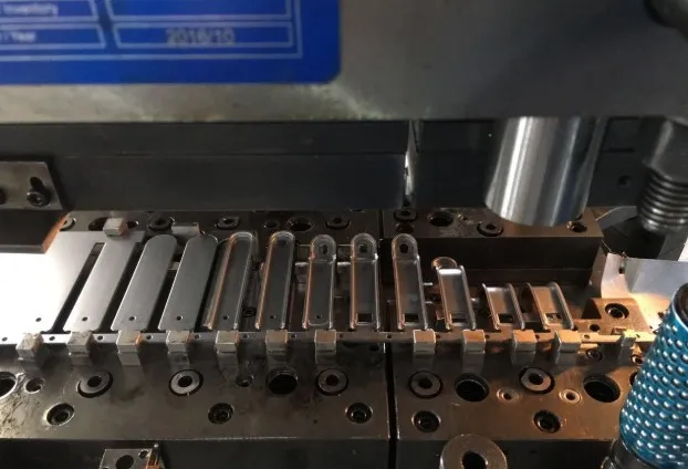
Plastic part design involves creating detailed plans for manufacturing plastic components. This includes material selection, structural integrity, and manufacturability to ensure high-quality, cost-effective production.
1 For stamping production, the structure of single-station molds is simple, the production efficiency is low, and the sheet metal parts cannot be too complicated, otherwise multiple single-station molds are required to achieve it. If progressive dies are used for stamping production, these shortcomings can be changed. The characteristics of progressive dies are high production efficiency, short production cycle, and few operators, which are very suitable for mass production.
2 Key points of progressive die design
2.1 Product expansion calculation and layout
2.1 Product expansion calculation and layout
After reading the product drawing, the expansion calculation should be performed first. The expansion size of the product is generally obtained through empirical formulas, and some are calculated through software. No matter which method is used, the calculation result should be guaranteed to be within the allowable range. Because once the expansion size is calculated incorrectly, the final product will definitely be unqualified, and it will be very troublesome to correct it. Therefore, the results of the expansion calculation should be verified to ensure that the expansion size is accurate.
The process of designing the layout drawing is the process of determining the mold structure. If the layout drawing is determined, the basic structure of the mold will also be determined. Therefore, when designing the layout, we should consider the overall situation in detail, not be limited by the local structure, and pay more attention to details. For example: when allocating each step of the workstation, we should not only consider which workstation is punching, which workstation is bending, and which workstation is forming, but also consider how the various inserts should be arranged, whether the arrangement space is sufficient, and whether there is any mutual influence between the various inserts. For the punching workstation, we should mainly consider how the punching force is evenly and reasonably distributed, whether the strength of the punching die can be guaranteed, and complex punching should be properly observed. For bending and forming workstations, we should consider whether it can be formed at one time. If we are not sure, we should add a step of top forming or empty step to facilitate mold adjustment. For products with high flatness requirements or easy to warp during forming, we should add a leveling workstation to ensure flatness.
When arranging the order of workstations, we should pay attention to the fact that there should be no influence between the front and back positions, otherwise the order of work should be adjusted. For example, when performing Z-shaped bending, if there is a punching hole on the Z-shaped bending and the punching position has a strict tolerance requirement, then the Z-shaped bending should be performed first, and then the punching should be performed, so as to ensure the position of the punching hole.
The last position of the progressive die is the most important position because it involves how the product is taken out of the mold. The general ejection methods mainly include blowing out and dropping, and some special products also require a robot to take out the parts. Regardless of the method, cutting is required. The size and position of the cutting point must be carefully considered because they not only affect the ejection of the mold, but also affect whether the strip material can be fed in stably and smoothly. If the blanking ejection method is adopted, the burr direction at the cutting point is opposite to that at other positions. This can only be determined after discussion with the product designer.
When designing the layout, on the premise of ensuring that the strip material can be fed in smoothly and stable production, the material width and pitch should be minimized to reduce the cost of sheet metal parts.
2.2 Insert design
(1) Punching punch
The shape of the punching punch is determined by the shape of the product. It can be a straight structure or a reinforced structure. The main fixing methods are: hanging table fixing, pin fixing, screw fixing. Pressing block fixing, top screw fixing. Among them, hanging table fixing is the safest and most reliable, pin fixing is not commonly used, and the other three fixing methods are mainly for quick replacement during maintenance. You can freely choose according to your needs.
The die cutting edge can be cut directly on the die plate, but for products with large output or high hardness, a die insert should be designed to facilitate maintenance. The fixing methods of the die insert are: hanging table fixing, screw fixing, and pressing block fixing.
When designing a die insert for single-side punching, in order to prevent the waste from floating up, the extrusion corner should be added on the non-punching side to squeeze the waste and prevent it from floating up, as shown in Figure 1.
(2) Bending insert.
The bending insert can be fixed by a hanging table or a screw. The gap between the bending convex and concave dies should be one material thickness. The head of the bending punch should be designed with an arc R angle to avoid scratching the product during bending (as shown in Figure 2). For the bending die with self-supporting bending, a correction rib should be designed near the bending line (as shown in Figure 3) to produce plastic deformation at the root of the product during bending, reduce springback, and ensure a 90° bending angle.
2.3 Template design
The standard progressive die template includes: unloading plate, fixed plate, concave template, upper die seat, and lower die seat.
Among them, the unloading plate, fixed plate, and concave template are the three key templates and are also indispensable for progressive dies. The fixed plate plays the role of fixing the punch; the unloading plate mainly plays the role of unloading, guiding, and pressing; the concave template can serve as the die cutting edge, and the die insert can also be inlaid on it. Four small guide pins are used to guide the three templates. The four small guide pins are fixed on the punch fixing plate. Four small guide pins are respectively set on the unloading plate and the concave template. The matching accuracy between the small guide pins and the small guide sleeves is accurately controlled to ensure the movement accuracy of the punch.
When designing a progressive die, one important thing is to design the yield. Generally, all subsequent stations such as bending or forming stations need to yield, and they must yield fully. Not only static yield, but also dynamic yield should be considered.
2.4 Design of other parts
In a progressive die, some auxiliary parts also play an important role in the smooth operation of the die.
(1) Guide pins. In a progressive die, guide pins have a great influence on the accuracy of the product. Generally, two holes are punched in the first station, and the subsequent stations use these two holes for double guidance, which can better ensure the accuracy of the product. When designing the guide pin, pay attention to controlling the length of the guide pin. When the mold is in a free state, the length of the straight arm part of the guide pin extending out of the unloading plate should be less than the thickness of the product, so that the material carrying phenomenon can be effectively avoided.
(2) When designing the feeding height, it should be ensured that the strip material will not be blocked by any inserts or ejector pins when it is stacked at this height. The floating feeding pin can not only lift the strip material, but also guide it. Its number and position should be determined accordingly according to the width and thickness of the strip material.
(3) Pick-up block and ejector pin. When the strip material is subjected to bending, cutting, stretching and other forming processes, a clamping force will be generated to make the strip material forming part clamped on the insert, making it difficult to demold. In order to ensure that the strip material bounces up smoothly, a lifting block or ejector pin should be designed at an appropriate position to eject the strip material by relying on the spring force. At the last station, the cut product sometimes adheres to the mold due to the action of the stamping oil, so the upper and lower molds of the last station should be designed with ejector pins to prevent the occurrence of stacking and damage to the mold.
In addition, in order to prevent the misfeeding and waste floating from damaging the mold, a misfeeding and waste floating sensing alarm device can be designed.
3 Troubleshooting in production
In the production of progressive dies, some faults may occur sometimes, which will affect production. The following are some solutions to common faults.
3.1 Increased burrs of products
After the mold has been produced for a period of time, the burrs of the produced parts will increase. At this time, the edges of the convex and concave dies should be checked. If the edges are found to be worn or chipped, they should be sharpened. After sharpening, a gasket of corresponding thickness should be placed on the convex or concave dies. After the concave die has been sharpened many times, it should be checked whether the straight wall of the edge has been ground away. If there is no straight wall of the edge, the concave die insert should be replaced. If the convex and concave dies are not worn, but the burrs on the parts are uneven, it is because the blanking gap has been offset. At this time, the gap should be adjusted.
3.2 Floating waste
In stamping production, the floating of waste is a major problem. It not only affects production, but also damages the mold. Generally speaking, scrap with regular shapes such as round or square is easy to float, while scrap with more complex shapes is less likely to float.
The following are some reasons for scrap floating and solutions.
(1) The blanking gap is large. If scrap often floats during the die trial stage, it means that the blanking gap is too large. The die should be remade and the blanking gap should be reduced. If scrap only floats occasionally, you can use electric spark discharge in the die cavity to increase the roughness.
(2) The surface of the punch is too smooth, and the scrap adheres to the punch under the action of atmospheric pressure. You can add air holes to the punch.
(3) Single-sided blanking causes scrap to float. Add sharp corners on the non-blanking side to squeeze the scrap.
(4) The stamping speed is high, and you should consider reducing the speed. If you cannot reduce the speed due to production needs, you can add a push rod to the punch to push the scrap down.
In addition, there are some human factors, such as insufficient demagnetization after the blade is cut, and excessive stamping oil is used during the production of the punch. These should be avoided as much as possible.
3.3 Overlapping phenomenon
In stamping production, after the last station completes the cutting, the production parts are not blown out of the mold in time, but remain on the mold, which is very likely to cause overlapping. Overlapping is very dangerous and can easily damage the mold. There are many factors that cause overlapping, such as insufficient blowing wind, the adhesion of stamping oil, and the production parts hanging on the ejector rod. In view of these factors, a variety of measures can be taken to prevent the occurrence of overlapping. For example, in stamping production, it is necessary to ensure that the blowing wind is strong enough. When designing the mold, the ejector rod is added to the concave mold plate and the unloading plate. The ejector rod on the concave mold plate should be designed to be larger, at least larger than the hole on the part, or simply adopt a material block structure to avoid the production parts hanging on the ejector rod. When designing the concave mold plate, on the premise of ensuring the punching strength, a wider slope should be designed at the end of the concave mold plate so that the production parts can slide out of the mold smoothly. In addition, when designing, it should also be considered that at the last station, the parts to be cut should be extended out of the concave plate or the slope by at least half, and the parts should be slid out of the mold by their own weight.
3.4 Blockage of leakage holes
In stamping production, if the leakage holes are blocked and not discovered in time, it is easy to damage the mold, causing the punch to break or the die to rupture. To prevent the leakage holes from being blocked and ensure smooth leakage, the size of the leakage holes must be squeezed well. For some small protruding parts, the size of the leakage holes should be appropriately enlarged; and for the blockage of the leakage holes caused by the rolling of waste materials, the size of the leakage holes should be reduced. When designing the mold, sufficient attention should be paid to the leakage holes. When designing the concave die pad, the concave die plate should be used as a reference to ensure that the leakage contour of the concave die pad is larger than that of the concave die plate. When designing the lower mold frame, the concave die pad should be used as a reference. And so on. Finally, it is necessary to ensure that the leakage hole of the mounting plate is smaller than the leakage hole of the machine tool. Otherwise, a slope should be opened on the lower mounting plate to ensure that the waste material finally slides into the leakage hole of the machine tool.
In addition, grinding of the die edge or excessive stamping oil will also cause the leakage hole to be blocked. Timely grinding or replacement of stamping oil should be reduced.
3.5 Poor feeding
Poor feeding may affect production at the least and damage the mold at the worst. The causes are as follows:
(1) The feeding pitch is different from the designed pitch during production, and the feeding pitch should be adjusted.
(2) The spacing between the lifting pins is too large, and the number of lifting pins should be increased.
(3) The strip lifting height is not enough, and the strip is easy to hook on the lifting block or the top rod. The strip lifting height should be increased.
(4) The feeding gap of the lifting pins is too small, and the strip feeding is not smooth. The gap should be appropriately enlarged.
(5) The strip is too wide and too thin, which is easy to cause warping. A lifting block should be added in the middle of the strip.
4 Conclusion
4 Conclusion
Design is the source. Although design only accounts for about 10% of the mold cost, it determines 70%-80% of the entire mold cost. Therefore, designers must consider the mold structure in detail, consider how to improve productivity, and how to facilitate maintenance. However, we cannot rely entirely on design. In actual production, we must analyze specific problems and adjust the mold according to the actual situation. It is also necessary to repair and maintain the mold in production. When repairing the mold, we should pay more attention to details, find out the root cause, and repair it. When disassembling and assembling the mold, we must be careful to prevent damage to the mold. Regular maintenance can greatly increase the life of the mold.
How To Design The Die Casting Mold To Help Extend The Life Of The Mold
Several Ways To Achieve Mirror Processing
Related Article
Fast sampling is the fastest way to win business in the hardware machining and plastic mold industries. Customers want a working sample in days, and a 3D printer delivers it, but only when you know how to print in 3d correctly.
how to print in 3d
Fast sampling is the fastest way to win business in the hardware machining and plastic mold industries. Customers often send an STL file and expect a working sample in days.
how to print an stl file