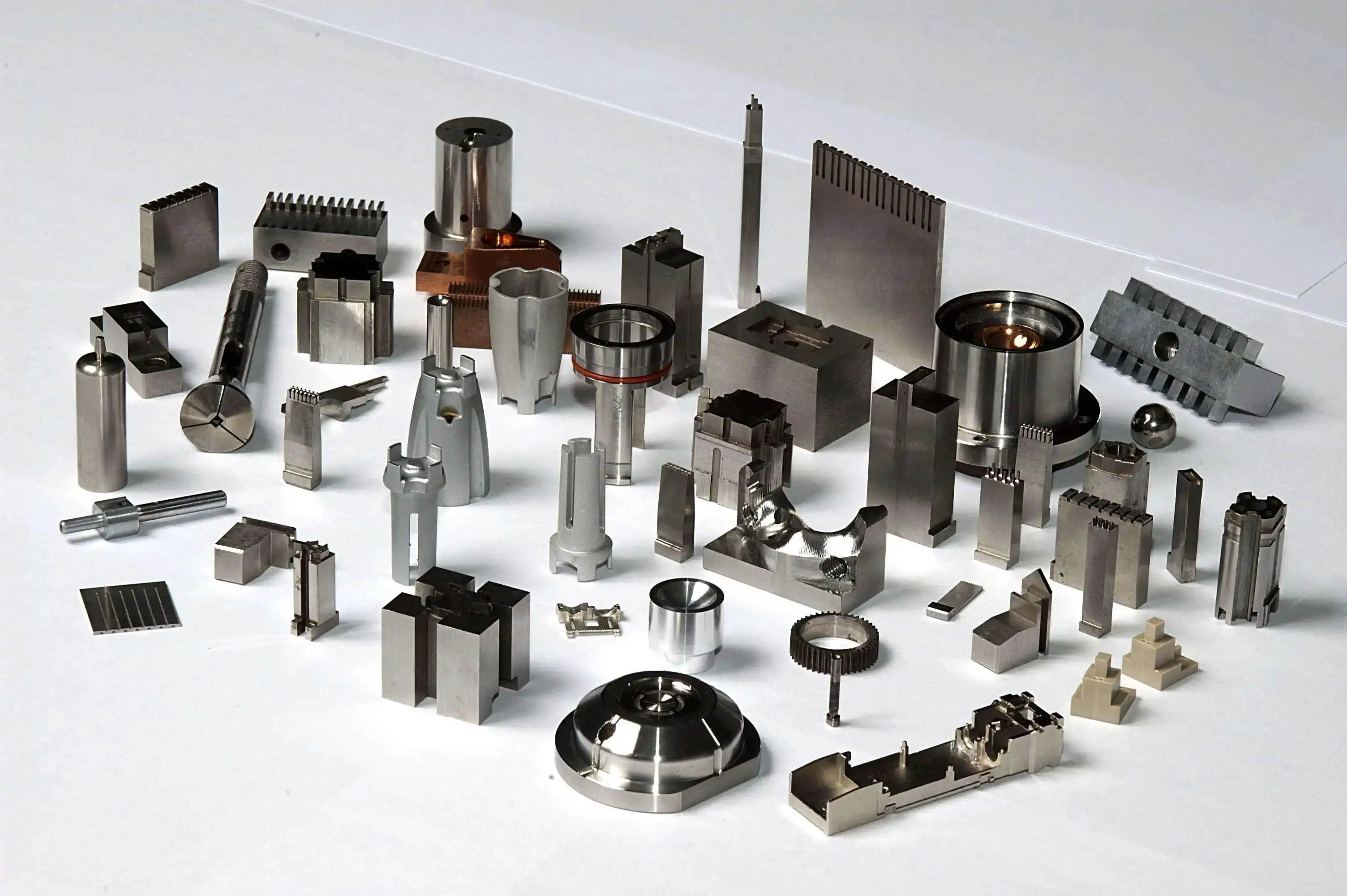
How to Design 3D Print Models: Complete Industrial Guide for Hardware & Mold Fast Sampling
Author: SZTC
2026-10-08
In modern hardware processing and plastic mold manufacturing, 3D printing has become the most efficient solution for rapid prototype verification, fixture testing and pre-production sampling. However, most printing failures, poor surface quality, structural deformation and assembly errors are not caused by printers or materials, but by improperly designed 3D models optimized for CNC machining or injection molding instead of additive manufacturing. For factory engineers and prototype designers who pursue stable, fast and low-cost industrial sampling, the core question is clear: how to design 3D print models that fit mold and hardware industrial standards. This article provides a systematic DfAM (Design for Additive Manufacturing) workflow tailored for real workshop rapid prototyping scenarios.
1. Shift From Traditional DFM to Industrial 3D Print Design
Before learning specific modeling skills, designers must rebuild their manufacturing logic. Understanding the essential differences between subtractive and additive design is the first step to master how to design 3D print models for qualified industrial samples.
1.1 Why Machining Models Fail for 3D Printing
Models created for CNC milling or injection molding allow ultra-thin walls, sharp internal corners, abrupt thickness changes and complex undercut structures. These features work well for material removal and mold opening but cause severe defects in layer-based 3D printing. Unoptimized traditional models often result in layer cracking, overhang collapse, warping and residual stress deformation, which greatly reduce the sampling yield rate for mold cavities and hardware fixtures.
1.2 Core Principles of Industrial 3D Print Model Design
Industrial 3D print model design follows three core principles: printability, structural stability and post-process friendliness. Every structural detail must adapt to layer stacking mechanics, thermal shrinkage rules and support logic. Unlike consumer decorative printing, mold and hardware model design prioritizes dimensional tolerance, mechanical performance and assembly accuracy to ensure printed samples can replace traditional machined parts for formal testing and verification.
1.3 Scenario-Based Design Differentiation
Plastic mold samples focus on surface smoothness, texture restoration and demolding simulation, while hardware prototypes prioritize structural strength, wear resistance and assembly matching. Qualified 3D print models must adopt differentiated structural strategies according to actual usage scenarios, which is the key to improving industrial sampling accuracy.
2. Fundamental Industrial Design Rules for 3D Print Models
Standardized parameter rules eliminate most printing defects. Mastering these industrial thresholds is the foundation ofhow to design 3D print models with high stability and repeatability.
2.1 Standardized Minimum and Uniform Wall Thickness
Wall thickness is the most critical parameter affecting print quality and structural strength. For SLA resin mold samples, the safe minimum wall thickness is 0.8mm to ensure complete texture restoration without hollow defects. For FDM hardware functional parts, walls must be thicker than 1.2mm to enhance layer bonding and prevent fracture. To control thermal stress and deformation, wall thickness variation should not exceed 50% of the nominal value. Avoid sudden thickening or thinning; use gradual transition structures to maintain overall uniformity.
2.2 Scientific Overhang and Self-Support Design
Follow the classic 45-degree self-support rule for industrial design. Structures with an inclination above 45 degrees can stack stably without auxiliary supports. For shallow overhangs below 45 degrees, redesign chamfers, add transitional slopes or adjust part orientation to reduce support coverage. Keep key mold texture surfaces and hardware assembly planes free from dense supports to avoid support marks and reduce post-polishing workload.
2.3 Stress Relief with Fillets and Transition Structures
Sharp internal right angles cause severe stress concentration during printing and usage, easily leading to layer separation and structural cracking. In industrial 3D model design, replace all sharp corners with rounded fillets. The fillet radius should be 25% to 50% of the local wall thickness to effectively disperse thermal stress and improve part toughness, especially for load-bearing hardware structures and repeatedly tested mold prototypes.
2.4 Tolerance Clearance and Shrinkage Compensation
All 3D printing materials produce different degrees of shrinkage during cooling and curing. When designing assembly holes, positioning grooves and sliding matching structures, reserve 0.1mm to 0.2mm clearance tolerance according to material characteristics. Resin requires minor compensation, while engineering plastics and metal powder need more precise offset settings to ensure the final printed sample meets industrial assembly standards.
3. Step-by-Step Workflow: How to Design 3D Print Models
This standardized full-process workflow completely answers how to design 3D print models for mold and hardware rapid sampling, covering design, optimization and final verification.
3.1 Clarify Sampling Requirements and Printing Processes
Start by confirming sample functions, precision requirements and testing standards. Select matching printing technology according to scenarios: SLA for high-precision mold appearance samples, FDM for low-cost hardware fixture prototypes, and metal printing for high-strength mold inserts. Different processes determine wall thickness, support rules and tolerance settings, guiding the overall design direction.
3.2 Build Printable Parametric Structures
Use industrial CAD software to build fully constrained parametric models. Remove unprintable traditional machining features such as ultra-thin residual walls, tiny blind holes and unreasonable undercuts. Optimize long flat structures and strip parts by adding reinforcing ribs to prevent bending deformation. For integrated hardware fixtures, combine multiple scattered parts into one-piece structures to eliminate assembly tolerance errors.
3.3 Optimize Internal and Surface Features
For plastic mold models, retain complete draft angles and cavity textures to simulate real injection molding demolding effects. Simplify non-functional decorative details while retaining cooling channels and key groove structures. For hardware models, optimize internal infill matching structures, design reasonable hollow and rib layouts, and balance lightweight performance and mechanical strength to meet strength testing demands.
3.4 Conduct Model Printability Simulation
Simulate layer stacking effects and stress distribution to check potential collapse, warping and cracking risks. Adjust local unreasonable structures in advance and optimize overhang angles and support positions. Ensure the model not only looks complete in design but also has stable molding performance in actual printing environments.
3.5 Final Inspection and Watertight Repair
A qualified 3D print model must be completely watertight and manifold. Inspect and repair open edges, overlapping faces and flipped normals to eliminate mesh defects. Confirm dimensional accuracy, structural rationality and post-processing feasibility to ensure the model can be directly exported and printed for industrial rapid sampling.
4. Scenario-Based Optimization for Mold and Hardware Models
Targeted optimization can greatly improve the success rate and practicability of industrial samples.
4.1 Plastic Mold 3D Print Model Optimization
Mold model design focuses on surface reduction restoration and demolding verification. Improve surface mesh smoothness, avoid abrupt curved surface transitions, and retain standard draft angles. Do not add excessive reinforcing ribs on cavity surfaces to prevent affecting injection molding simulation effects. Ensure the printed sample can truly reflect mold flow, demolding and assembly performance.
4.2 Hardware Functional 3D Print Model Optimization
Hardware model design emphasizes structural durability and assembly precision. Strengthen wall thickness at load-bearing joints and connection holes, and optimize stress concentration areas. For threaded holes and mounting positions, reserve standard installation tolerances and design heat-stake insert structures reasonably to improve connection stability, making printed fixtures fully functional for workshop testing.
5. Common 3D Print Model Design Mistakes to Avoid
Avoiding typical errors can effectively reduce rework rates and save sampling time and material costs.
5.1 Blindly Using Traditional Machining Structures
Directly applying CNC and injection molding design rules leads to unprintable features, serious deformation and insufficient structural strength, resulting in large-area sample scrapping.
5.2 Unreasonable Overhang and Support Dependence
Excessive overhanging structures rely heavily on supports, leaving a large number of surface marks that affect mold appearance simulation and hardware assembly precision, and increase post-processing difficulty.
5.3 Ignoring Shrinkage and Tolerance Matching
Unreserved shrinkage compensation and unreasonable clearance settings cause dimensional deviation, making qualified design drawings produce unqualified printed samples that cannot be assembled and tested normally.
6. Conclusion
In short, the core answer to how to design 3D print models for mold and hardware rapid sampling is to implement comprehensive DfAM optimization. Qualified industrial 3D print models require standardized wall thickness, scientific overhang layout, reasonable stress relief and accurate tolerance compensation, completely breaking the limitations of traditional subtractive manufacturing design thinking. Mastering this complete design workflow can effectively improve printing yield, shorten product iteration cycles, and provide high-precision, high-strength rapid prototypes for plastic mold verification and hardware functional testing, helping manufacturing enterprises improve market response efficiency and core competitiveness.


Samuel Song Your service representative
samuel@chnzhongzhu.com WhatsApp:+86 18688963321
Specializing in zinc-aluminum-magnesium alloy die-casting processing, CNC milling, CNC turning, 3D printing, injection molding and sheet metal processing. Manufacturing services.
How to Design a 3D Print Model: Industrial DfAM Guide for Hardware & Mold Rapid Sampling
How to Create STL Files: Industrial Step-by-Step Guide for Hardware & Mold Rapid Sampling
Related Article
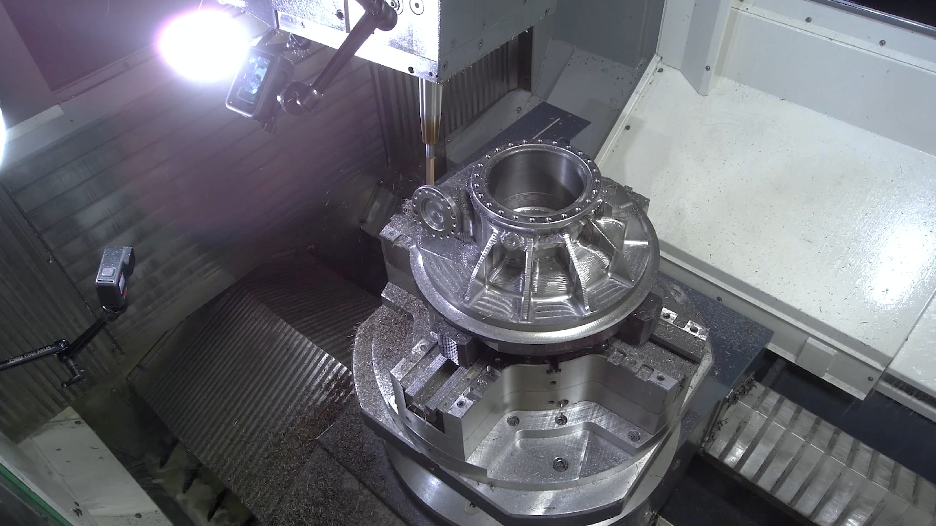
Grinding is not just a finishing touch for auto parts. It is a critical precision machining stage that determines sealing performance, noise level, service life and fatigue resistance of rotating automotive parts.
a grinding machine in an auto parts plant
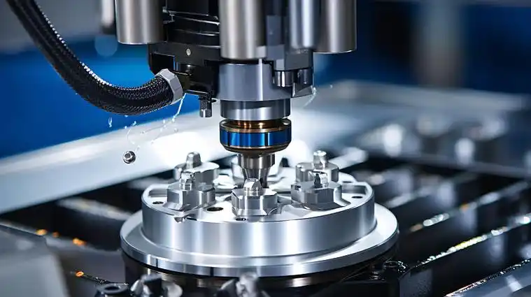
This guide explains what stresses act on cast iron machine parts, the unique material properties of cast iron, common cast iron grades, CNC machining considerations, failure modes, and how you can evaluate a qualified cast iron machining supplier.
A cast iron machine part is acted upon?
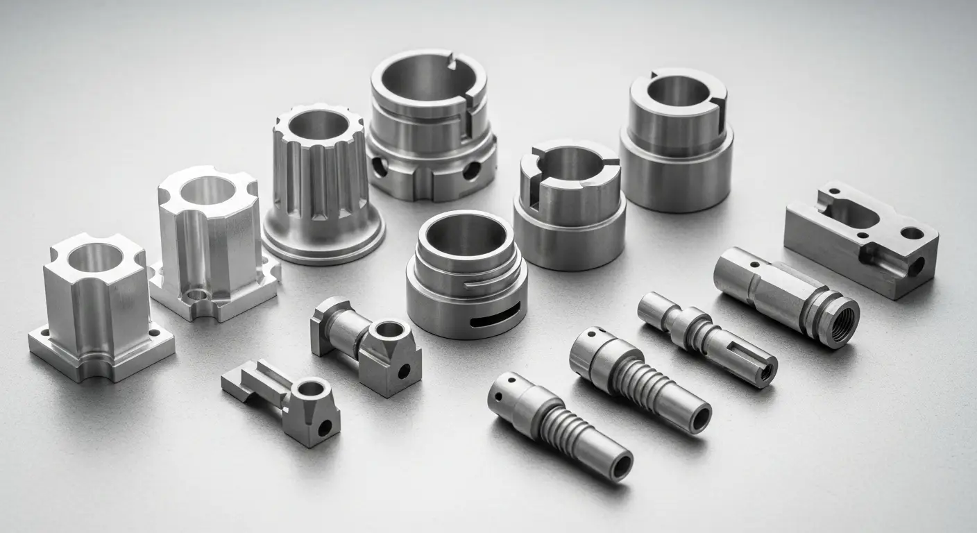
Power transmission is not a single bolt-on component. It forms the motion chain between your prime mover and cutting/feeding units. For machine shops and equipment builders, transmission quality directly determines spindle runout, positioning repeatability and surface finish of machined workpieces.
what part of a machine is the power transmission?