how to avoid poor surface finishes on machined parts?
How to Avoid Poor Surface Finishes on Machined Parts: A Practical CNC Machining Guide
Surface finish is an important quality characteristic in CNC machining. It affects not only the appearance of a machined component but also its functionality, assembly performance, wear behavior and, in some applications, sealing or contact performance. A component may meet its dimensional requirements and still be unsuitable if its surface condition does not meet the engineering specification.
For manufacturers and purchasing teams, understanding how to avoid poor surface finishes on machined parts is essential when developing a reliable production process. Surface defects can result from several factors, including unsuitable cutting parameters, worn tools, machine vibration, poor workholding, material characteristics and inadequate inspection.
Quick answer: To avoid poor surface finishes on machined parts, select suitable cutting tools, optimize cutting speed and feed rate, maintain a stable machining setup, control vibration, use appropriate coolants or lubricants where required, and inspect the finished surfaces against clearly defined specifications.
Surface quality should be managed throughout the manufacturing process rather than checked only after machining is complete.
Table of Contents
- 1. What Is Surface Finish in CNC Machining?
- 2. Common Causes of Poor Surface Finishes
- 3. How to Avoid Poor Surface Finishes on Machined Parts
- 4. Choosing the Right Machining Parameters
- 5. Cutting Tools and Material Selection
- 6. How to Inspect Surface Finish
- 7. Design Considerations for Better Surface Quality
- 8. Surface Finish Quality Control Checklist
- 9. Frequently Asked Questions
- 10. Conclusion and Quote Request
1. What Is Surface Finish in CNC Machining?
Surface finish describes the texture and condition of a machined surface. It includes the small peaks, valleys, tool marks and other irregularities left behind by the manufacturing process. These characteristics can influence how a component looks, fits, moves or interacts with another surface.
In engineering drawings, surface texture requirements are often expressed using surface roughness parameters. One commonly used parameter is Ra, or the arithmetic average roughness. It represents the average absolute deviation of a surface profile from its mean line over a specified evaluation length.
Common Surface Roughness Parameters
| Parameter | Meaning | What It Helps Describe |
|---|---|---|
| Ra | Arithmetic average roughness | Average profile deviation from the mean line |
| Rz | Maximum height of the profile over specified sampling lengths, according to the applicable standard | Surface peak-to-valley characteristics |
| Rt | Total height of the profile over the evaluation length | Overall profile height, including the highest peak and deepest valley |
Ra is widely used, but it does not describe every aspect of surface texture. Two surfaces with the same Ra value may have different peak shapes, valley patterns or directional tool marks. For this reason, the correct roughness parameter and measurement method should be specified according to the component's function and applicable engineering requirements.
2. Common Causes of Poor Surface Finishes
Poor surface quality rarely has only one possible cause. It often results from a combination of cutting conditions, tooling, machine stability and process control. Identifying the actual cause is the first step toward selecting an effective corrective action.
2.1 Incorrect Cutting Parameters
Cutting speed, feed rate and depth of cut influence the way a cutting tool interacts with the workpiece. An unsuitable combination can cause excessive tool marks, unstable cutting, heat generation or poor chip formation. For example, an excessively high feed per tooth in milling can leave more pronounced feed marks on the machined surface.
2.2 Worn or Unsuitable Cutting Tools
A worn cutting edge may rub against the material instead of cutting it cleanly. This can increase cutting forces, generate heat and produce rough or inconsistent surfaces. Tool material, geometry, coating and edge condition should be appropriate for the workpiece material and machining operation.
2.3 Machine Vibration and Chatter
Vibration can leave visible patterns or repeated marks on a machined surface. Chatter may occur when the cutting process becomes dynamically unstable, often due to tool overhang, workpiece flexibility, inadequate clamping, unsuitable cutting parameters or machine-tool condition.
2.4 Poor Workholding and Setup
If a workpiece moves, flexes or vibrates during machining, the cutting tool may not maintain a consistent relationship with the intended surface. Insufficient clamping, unsuitable fixture design and excessive unsupported length can all contribute to surface defects.
2.5 Material-Related Problems
Different materials respond differently to machining. Material hardness, microstructure, inclusions, ductility and consistency can influence chip formation and the final surface. Some materials are more prone to built-up edge, tearing or smearing under unsuitable cutting conditions.
2.6 Inadequate Coolant or Lubrication
Depending on the material and machining operation, insufficient or poorly directed coolant can contribute to heat buildup, chip recutting and unstable cutting conditions. The appropriate coolant or lubrication strategy should be selected for the specific process rather than applied as a universal solution.
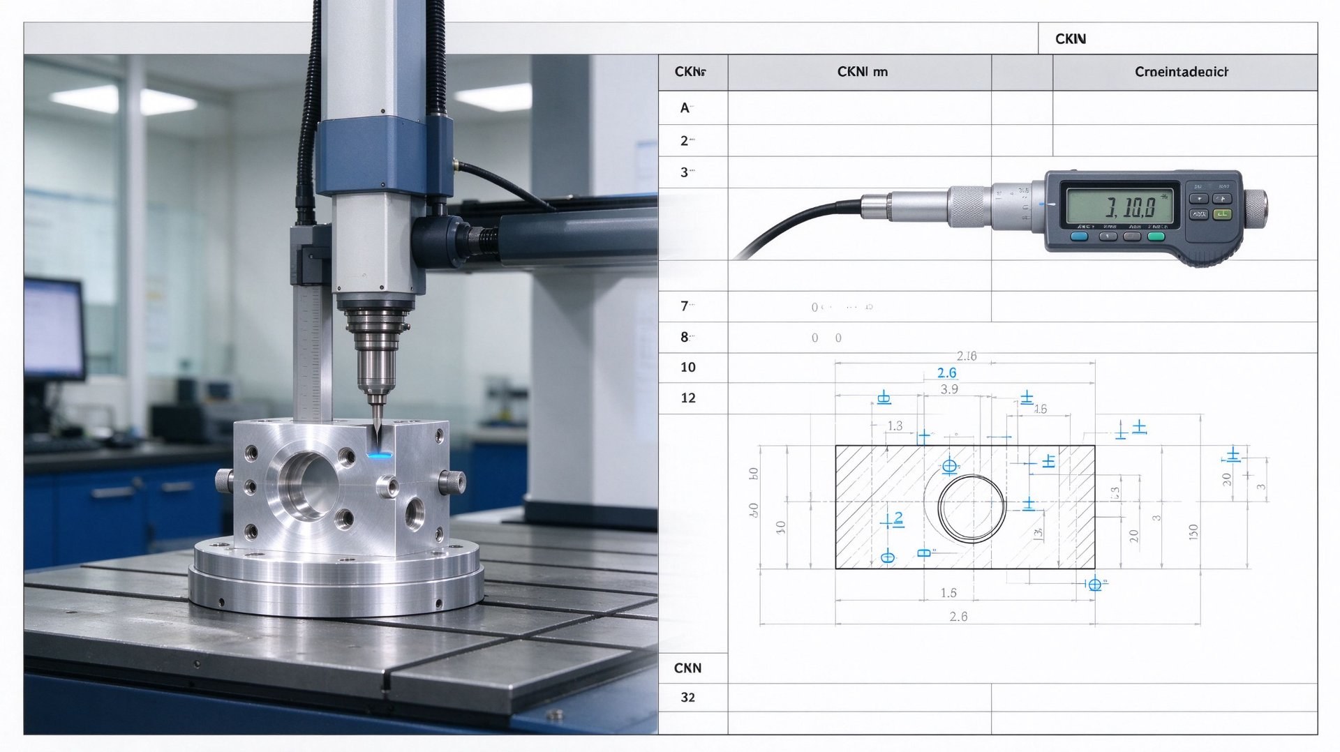
3. How to Avoid Poor Surface Finishes on Machined Parts
Preventing surface defects requires a controlled machining process. The following practices help manufacturers improve surface consistency and reduce the risk of rework or rejected parts.
3.1 Select the Correct Cutting Tool
Choose a tool that matches the workpiece material, machining operation and required surface quality. Consider tool geometry, cutting-edge sharpness, substrate, coating and the manufacturer's recommended operating conditions.
- Use suitable tool geometry for the material and operation.
- Check cutting edges for wear, chipping or damage.
- Use an appropriate nose radius for the intended turning operation.
- Replace or recondition tools when their condition affects process stability.
- Avoid using a tool beyond its practical service life.
3.2 Optimize Feed Rate and Cutting Speed
Cutting parameters should be selected based on the material, tool specification, machine capability and machining strategy. A lower feed rate can improve surface finish in some operations, but simply reducing the feed is not always the right solution. Excessively low feed may cause rubbing or inefficient cutting, depending on the tool geometry and process.
Begin with appropriate tooling recommendations and validate the parameter combination through controlled trials. Where surface quality is critical, evaluate the actual measured result rather than relying only on theoretical calculations.
3.3 Reduce Vibration and Chatter
Stable machining is essential for a consistent surface. Vibration can be reduced by improving workholding, minimizing tool overhang, selecting suitable cutting conditions and checking machine-tool condition.
- Keep tool overhang as short as practical.
- Use rigid and appropriate workholding fixtures.
- Ensure the workpiece is properly supported.
- Check toolholders, spindle condition and machine maintenance status.
- Adjust cutting parameters when chatter or unstable cutting is detected.
3.4 Maintain Proper Coolant and Chip Control
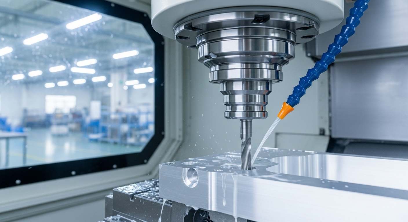
Coolant selection and delivery should suit the machining operation and material. Effective chip evacuation helps prevent chips from being trapped between the tool and the workpiece, where they can scratch or damage the finished surface.
Check coolant concentration and condition where applicable, and ensure that the coolant reaches the cutting zone effectively. Dry machining may also be appropriate for certain materials and operations when the process is designed and validated for it.
3.5 Use Suitable Finishing Operations
A roughing operation is generally intended to remove material efficiently, while a finishing operation focuses on achieving the final dimensions and surface characteristics. Separating these stages can help reduce the influence of heavy cutting forces on the final surface.
Depending on the component, finishing strategies may include a dedicated finishing pass, precision turning, fine milling, grinding or other secondary processes. The selected method should be based on the drawing requirements, material and component function.
3.6 Inspect the First Article and Monitor Production
Surface quality should be verified during process development and production. First-article inspection helps confirm that the machining setup can meet the specified requirements before the process continues at volume.
Periodic checks can also reveal gradual tool wear, changes in machine condition or material variation before these issues affect a large number of parts.
4. Choosing the Right Machining Parameters
Machining parameters have a direct influence on surface formation. However, there is no single cutting speed or feed rate that guarantees a good surface finish for every component. Parameters must be evaluated as a complete process combination.
| Process Factor | Potential Surface Quality Risk | Recommended Control |
|---|---|---|
| Feed rate | Pronounced feed marks or an unsuitable cutting action | Optimize feed according to tool geometry, material and operation |
| Cutting speed | Excessive heat, built-up edge or unstable cutting under unsuitable conditions | Follow tool recommendations and validate the cutting condition |
| Depth of cut | High cutting forces or vibration in an unsuitable setup | Balance material removal, rigidity and process stability |
| Tool overhang | Deflection and chatter | Minimize unsupported tool length where practical |
| Coolant delivery | Heat buildup or poor chip evacuation | Use a suitable coolant strategy and maintain delivery conditions |
| Tool condition | Rubbing, tearing, inconsistent tool marks | Monitor wear and replace damaged or unsuitable tools |
Roughing and Finishing Should Be Managed Separately
During roughing, the priority is usually efficient material removal while maintaining acceptable stability. During finishing, the priority shifts toward dimensional control and the required surface texture.
A finishing pass should use a suitable tool and a stable setup. The remaining stock allowance must also be controlled: too little material may not allow the tool to clean up the surface, while too much may create unnecessary cutting forces or affect the finishing strategy.
5. Cutting Tools and Material Selection
Tool selection and workpiece material are closely connected. A tool that performs well on one alloy may not provide the same surface quality on another. Manufacturers should consider both the material's machining behavior and the surface requirements of the finished component.
5.1 Match Tool Geometry to the Material
Cutting-edge geometry influences chip formation, cutting forces and the interaction between the tool and the workpiece. Tool manufacturers provide different geometries for different material groups and operations. Selecting an appropriate geometry helps reduce rubbing, unstable chip formation and excessive cutting forces.
5.2 Consider Material Machinability
Aluminum alloys, stainless steels, carbon steels, copper alloys and engineering plastics can behave differently during machining. For example, some ductile materials may be prone to built-up edge or surface smearing, while certain plastics may be sensitive to heat and deformation.
Material grade, condition and consistency should therefore be confirmed before production. If a component has particularly demanding surface requirements, a trial using the intended material grade can help validate the proposed process.
5.3 Keep Cutting Tools in Good Condition
Tool wear should be monitored according to the machining process and production requirements. Visual inspection, tool-life records and surface measurements can help identify when a tool is no longer producing consistent results.
6. How to Inspect Surface Finish
A reliable surface finish control plan needs clear acceptance criteria and suitable inspection methods. Visual inspection is useful for identifying obvious defects, but it cannot replace quantitative measurement when a drawing specifies a roughness value.
6.1 Visual Inspection
Visual inspection can help identify scratches, dents, burrs, chatter marks, discoloration and other visible surface defects. Lighting conditions and inspection consistency should be controlled, particularly when appearance is part of the acceptance criteria.
6.2 Surface Roughness Measurement
A contact surface roughness tester, also known as a profilometer, can measure parameters such as Ra and Rz. The measurement setup should follow the applicable standard and account for the correct evaluation length, cutoff, measurement direction and surface location.
6.3 Coordinate and Dimensional Inspection
Dimensional inspection is separate from roughness measurement, but it is often important when evaluating a finished machined component. Critical dimensions, geometric tolerances and surface requirements should each be checked using suitable equipment and methods.
| Inspection Method | Main Purpose | Important Consideration |
|---|---|---|
| Visual inspection | Identify visible defects and appearance issues | Use consistent lighting and agreed visual criteria |
| Surface roughness tester | Measure specified roughness parameters | Follow the correct measurement standard and settings |
| Dimensional measuring tools | Verify component dimensions | Use suitable calibrated measuring equipment |
| Coordinate measuring machine | Inspect selected dimensions and geometric characteristics | Use an appropriate measurement program and datum strategy |
7. Design Considerations for Better Surface Quality
Surface finish is not determined by machining alone. Part geometry, drawing requirements and product function can also influence how easily a manufacturer can achieve the required result.
7.1 Specify Surface Requirements Clearly
Identify which surfaces are functionally important and which require a specific roughness value. Not every surface needs the same finish. Applying unnecessarily tight requirements across an entire component may increase manufacturing time and cost without providing a functional benefit.
7.2 Consider Tool Access and Part Geometry
Deep pockets, narrow slots, thin walls and difficult internal features can limit tool access or reduce setup rigidity. These features may make it harder to control vibration, tool deflection and chip evacuation.
7.3 Define Post-Machining Requirements
Some components require deburring, polishing, grinding, blasting, anodizing, plating or painting after machining. These processes may change the final surface appearance or texture. The drawing should clarify whether the roughness requirement applies before or after the relevant finishing treatment.
7.4 Review Critical Surfaces During DFM
A design-for-manufacturing review can help identify difficult-to-machine surfaces, unclear tolerances and requirements that may increase production complexity. Discussing these points before production can reduce the risk of late changes and avoidable quality issues.

8. Surface Finish Quality Control Checklist
The following checklist can be used during process planning, first-article inspection and ongoing production control.
| Control Stage | Key Checks |
|---|---|
| Before machining | Confirm material grade, drawing revision, surface requirements and machining allowance. |
| Tool preparation | Verify tool type, geometry, edge condition and toolholder setup. |
| Machine setup | Check workholding rigidity, tool overhang, spindle condition and machine stability. |
| Parameter validation | Confirm cutting speed, feed rate, depth of cut and coolant strategy. |
| First-article inspection | Inspect critical dimensions, specified surface roughness and visible surface defects. |
| Production monitoring | Track tool wear, process consistency and inspection results across batches. |
| Final inspection | Verify all agreed surface and dimensional acceptance requirements before delivery. |
Keeping records of process settings and inspection results helps manufacturers identify recurring defects and improve process repeatability. When a surface problem occurs, compare affected parts with previously accepted samples and review changes in tooling, material, setup and machining conditions.
9. Frequently Asked Questions
Q1: What causes poor surface finishes on machined parts?
Common causes include incorrect cutting parameters, worn tools, machine vibration, unsuitable workholding, poor chip evacuation and material-related machining problems. The actual cause should be identified through process inspection and testing.
Q2: How can I improve the surface finish of CNC machined parts?
Start by checking the cutting tool and its condition, then review feed rate, cutting speed, depth of cut and machine stability. Improve workholding and chip evacuation where necessary, and use a suitable finishing operation if the required surface quality cannot be achieved during roughing.
Q3: Does a lower feed rate always produce a better surface finish?
No. A lower feed rate can reduce feed marks in some operations, but excessively low feed may cause rubbing or other undesirable cutting conditions. The correct feed depends on tool geometry, material, cutting speed and the machining strategy.
Q4: Can worn cutting tools cause rough surfaces?
Yes. Worn or damaged cutting edges can increase friction and cutting forces, produce inconsistent tool marks and affect dimensional accuracy. Tool condition should be monitored and tools replaced when their wear affects process performance.
Q5: What is the difference between Ra and Rz?
Ra represents the arithmetic average roughness of a measured profile, while Rz describes profile height characteristics according to the applicable measurement standard. They provide different information, so one should not automatically be substituted for the other.
Q6: Can machine vibration affect surface quality?
Yes. Vibration and chatter can create repeated patterns, waviness or irregular marks on the machined surface. Improving fixture rigidity, reducing tool overhang and optimizing cutting conditions can help control these problems.
Q7: Is polishing necessary for every CNC machined part?
No. Polishing is only necessary when required by the component's function, appearance or engineering specification. Many machined components can meet their requirements directly through an appropriate machining and finishing process.
Q8: How do manufacturers measure surface roughness?
A surface roughness tester or profilometer is commonly used to measure parameters such as Ra and Rz. The measurement method, settings and inspection locations should follow the applicable standard and drawing requirements.
Q9: Does material selection affect the final surface finish?
Yes. Different materials have different hardness, ductility, microstructure and machining characteristics. These properties influence chip formation, tool wear and the ability to achieve a consistent surface finish.
Q10: What should I include when requesting a CNC machining quotation?
Provide the latest 2D drawing, 3D model where available, material specification, required quantity, critical dimensions, surface roughness requirements, applicable standards and any post-machining finishing requirements. Clear technical information helps suppliers evaluate manufacturability and quotation requirements.
10. Conclusion: Achieving Consistent Surface Finishes on Machined Parts
Avoiding poor surface finishes on machined parts requires more than selecting a suitable CNC machine. It involves controlling the entire machining process, from material selection and tool preparation to cutting parameters, workholding, chip evacuation and final inspection.
Manufacturers should define surface requirements clearly, validate the machining process before production and monitor tool and machine conditions throughout the manufacturing cycle. When a surface defect appears, identifying its root cause is more effective than making random parameter adjustments.
For buyers and engineering teams, early communication with the machining supplier is equally important. Providing clear drawings, material specifications and surface finish requirements helps the supplier assess manufacturability and develop a more reliable production plan.
If you are sourcing CNC machined components, Shenzhen Zhongzhu Technology welcomes the opportunity to review your drawings and discuss your manufacturing requirements.
Looking for a Reliable CNC Machining Partner?
Shenzhen Zhongzhu Technology Co., Ltd. provides manufacturing solutions for metal and plastic components, including CNC machining, die casting, stamping and injection molding.
Send us your 2D drawings, 3D files and technical requirements. Our team can review your project information and discuss suitable manufacturing options.
Contact Our TeamAddress: 315 PING 'AN AVENUE, PINGHU STREET, LONGGANG DISTRICT, SHENZHEN CITY, GUANGDONG PROVINCE
Phone: +86 18688963321
Email: samuel@chnzhongzhu.com
Website: www.chnzhongzhu.com
Contact: About Us | Our Services


are multi-spindle machined parts lower quality?
Related Article