Differential Pressure Casting Of Large Complex Magnesium Alloy Shell Castings
The large and complex ZM5 magnesium alloy shell castings were prepared by using differential pressure casting, and the temperature field of the castings was simulated using MAGMA software. To solve the metallurgical quality problem of castings, it is proposed to adopt a hemispherical design for the upper part of the riser pipe during differential pressure casting, which can increase the contact area between the molten metal entering the riser pipe and the cavity, thereby increasing the heated area and reducing the molten metal The thermal shock to the moulding sand greatly reduces the sand rolling problem caused by the long-term thermal shock, to obtain high-quality castings.
Compared with gravity casting, in differential pressure casting, the melt is filled from the bottom of the mould into the cavity, the alloy liquid flows smoothly and is poured in a closed container, and there are fewer defects such as oxidation and inclusions; the differential pressure casting is after the melt is filled with the cavity It will continue to maintain the pressure of the gas on the liquid surface, and even increase the holding pressure, the feeding effect is good, and the gradual density is higher than that of sand castings; the gating system of differential pressure casting is relatively simple, and it can even be simplified without a riser. In addition to the technological process, the utilization rate of the metal melt is also high.
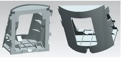
Taking the ZM5 large-scale multi-rib wall thickness difference complex curved shell casting as the research object, the shell size is about 620mm×650mm×420mm. During the solidification process, the thick and thin junctions and the ribs are prone to "hot joints" and other problems, resulting in the inability to guarantee the simultaneous solidification or sequential solidification of the molten metal, and poor feeding, so defects such as looseness and cracks will occur; for mechanical processing, both To ensure the accuracy of the curved surface, it is also necessary to ensure the relative positional relationship between the curved surface elements. Therefore, it is quite difficult to produce the casting.

Figure 1 Schematic diagram of shell casting
1 ZM5 Magnesium alloy casting gating system and sand mould design
To ensure the internal quality of the casting, it is necessary to create an effective condition conducive to sequential solidification according to the structural characteristics of the casting. At present, the methods used to estimate the solidification time of castings mainly include the modulus method, the thermal circle method, the empirical method, and the thermal modulus method. Since the modulus method relatively considers the influence of the structural shape of the casting on the heat dissipation conditions, it is more accurate than the thermal pitch method and empirical method in estimating the solidification time of the casting, so the modulus method has been widely used in the casting field. . Figure 2 is a cloud diagram of the simulated casting module distribution. The large part of the casting with a large modulus is concentrated on the large flat position at the bottom of the casting, so choosing the large flat face down is good for feeding. Due to the high height of the casting, it is impossible to fill the mould with conventional runners, so 4 slot runners are placed on the side of the casting to ensure the filling. According to the structural characteristics and complexity of the castings, the pouring and sand moulds are designed as shown in Figure 3.

Figure 2 Casting module cloud diagram

Figure 3 The gating system and sand mould design and assembly during differential pressure casting
2 Simulation of differential pressure casting ZM5 magnesium alloy castings
2.1 the Filling process of castings
Fig. 4 is a numerical simulation of the material tracing of the filling process of the studied casting according to the gating system shown in Fig. 3 for the material tracing of the filling process. It can be seen from the figure that the molten metal first enters from the riser nozzle and diverges through the four horizontal runners under the gating system. When flowing in the runner and entering the 4 vertical runners on the side of the casting cavity, the liquid at the corner will have a greater impact after touching the wall, and there will be backflow. This position is also very easy to roll sand. As the level of molten metal rises in the 4 vertical runners and enters the casting cavity through the inner gate, the filling of the large surface of the bottom of the casting is first completed, and then the vertical runner level rises to complete the filling of the side of the casting, Until the top cavity of the casting is filled, it can be found from Figure 3 that the method of using differential pressure casting is more uniform.


Figure 4 Material tracing of castings in the filling process during differential pressure casting
2.2 Analysis of the temperature field of the casting
Figure 5 shows the simulation results of the temperature distribution law of the solidification process of large-scale thin-walled magnesium alloy castings. At the end of filling, the entire cavity is basically in a liquid state, but there is a small amount of solidification in the extremely thin position, but it has also been filled. As the solidification progresses, generally speaking, the molten metal in the casting cavity solidifies first, followed by the upper riser, then the upper part of the four runners on the sidewall solidify, and finally, the lower part of the runner solidifies, followed by filling. As the solidification progresses, the temperature at the sidewall and the junction between the sidewall and the bottom decreases very rapidly. This part solidifies first. As the solidification progresses, the solid phase ratio of this part is higher, and the formed dendrites will block and shrink. Channel, so that the bottom large surface centre area is blocked, and it is predicted that there is a possibility of defects in this area. In addition, the inner gate attachments of the 4 vertical runners shrink as the solidification progresses, which is also a place where defects are more likely to occur. Therefore, the size of the 4 runners on the side can be appropriately enlarged when designing the 4 runners on the side.


Figure 5 Temperature field during solidification of castings during differential pressure casting
2.3 Analysis of the solidification process of castings
Figure 6 shows the time for the molten metal in the differential pressure casting cavity to transform from the liquid phase to the solid phase. It takes a longer time for the four vertical runners on the side of the cavity to change from the liquid phase to the cavity. The long-term high temperature will cause the structure of the place to become coarse, which will lead to the formation of looseness during solidification and shrinkage, and micro-cracks in severe cases. Figure 7 shows the time required for solidification and shrinkage at the hot joint of the casting during differential pressure casting. The position where the solidification and feeding time is relatively long at the hot joint appears at the position where the side vertical runner and the cavity are in contact, which is also the reason why defects are very easy to appear in the actual production process.

Fig. 7 Feeding and solidification time at hot joints of castings during differential pressure casting
Figure 8 shows the temperature distribution when the molten metal enters the runner at the bottom of the pouring system during differential pressure casting. The temperature of the alloy liquid in the riser tube increases. During the filling process of the riser, the moulding sand on the upper part of the riser tube has to be impacted for a long time. The impact of the moulding sand at a high temperature for a long time will easily cause the moulding sand to fall off and enter the cavity of the casting with the liquid. middle. In addition, it can also be seen that the alloy liquid flows in the bottom runner. When it touches the 4 vertical runners, there will be refluxed alloy liquid, which is very easy to form entrainment defects. At the same time, the molten metal will impact the vertical runner for a long time. The sidewall is also easy to cause sand rolling.

Figure 8 Temperature field when molten metal enters the runner at the bottom of the pouring system during differential pressure casting
Figure 9 shows the process of solidification at the end of the filling in the differential pressure casting. At a certain point in the solidification process, there are isolated high-temperature liquid phase regions at the umbilicus on both sides of the casting, so it is easy to not get the vicinity during the solidification and shrinkage process. The shrinkage of the gap can easily form shrinkage holes or shrinkage defects.

Fig. 9 Liquid fraction at the position of the umbilicus on both sides of the casting at a certain moment in the solidification process during differential pressure casting

Figure 10 Liquid fraction of the bottom surface of the casting at a certain point in the solidification process during differential pressure casting
Figure 10 shows that as the solidification progresses at the end of the filling in the differential pressure casting, at a certain point in the solidification process, there is an isolated high-temperature liquid phase area at the bottom of the casting, so it is very easy to not get the nearby gaps during the solidification and shrinkage process. Feeding can easily form shrinkage holes or shrinkage defects.

Figure 11 The distribution of solidification time in different areas after the filling of the mould in differential pressure casting
Figure 11 shows the solidification time distribution in different areas after the filling is completed during differential pressure casting. The area with a longer solidification time is mainly concentrated in the part where the vertical runner gap and the casting intersect, as shown in the black box mark position. This further shows that the alloy liquid in the part of the area where the vertical runner gap intersects the casting is overheated for a long time, the dendrite grows coarsely, and it is easy to form loose defects. This has the same changing law as the Hot Sport Fstime hot joint feeding solidification time simulated in Fig. 8.
2.4 Inclusion analysis of castings
Figure 12 shows the temperature field when molten metal enters the bottom area of the cavity during differential pressure casting. It can be seen that when the molten metal fills the large area of the bottom surface of the cavity, most of the front end alloy liquid enters the bottom plate area of the casting. This part of the alloy liquid contains a lot of impurities and is easy to form inclusion defects.

Figure 12 Temperature field when molten metal enters the bottom area of the cavity during differential pressure casting
Fig. 13 is a material trace distribution diagram of castings at the end of punching during differential pressure casting. After the material tracer enters the cavity, the tracer particles stay in the yellow area of the bottom plate for a longer time. That is to say, during the casting process of molten metal, most of the molten metal that has just entered the cavity enters the bottom of the cavity, and the molten metal that has just entered the bottom of the cavity also generates or contains a large number of impurities, so it is very easy to be in the casting. Defects such as inclusions are formed at this position.

Figure 13 The material trace of the casting at the end of filling in the differential pressure casting
3 According to the simulation results of differential pressure casting ZM5 magnesium alloy castings, the process plan is optimized
3.1 Process plan optimization for sand volume, inclusions and porosity issues
Aiming at the problems in the above casting simulation process, the pouring scheme was optimized, as shown in Figure 14 and Figure 15.

Figure 14 Schematic diagram of the hemispherical design of the sand mold on the upper part of the riser pipe of the differential pressure casting

Figure 15: Schematic diagram of the extended design of the runner for the lower part of the flow during differential pressure casting
Figure 14 is a schematic diagram of the hemispherical design of the sand mold on the upper part of the riser pipe during differential pressure casting. This design method can increase the contact area between the molten metal entering the riser pipe and the cavity, thereby increasing the heated area and reducing the impact of the molten metal on the molding sand. Thermal shock, thereby greatly reducing the aforementioned sand rolling problem caused by long-term thermal shock. Figure 15 is a schematic diagram of the extended design of the runner for the lower part of the flow during differential pressure casting. This design method has two advantages. First, the molten metal enters the horizontal runner through the riser pipe, and has a buffering effect before entering the vertical runner to avoid rapid thermal shock and cause the absence of sand rolling. Secondly, this kind of extension design can also make the molten metal with inclusion defects that existed or generated in the riser first enter the extension section first, which can greatly reduce the entry of unclean molten metal into the cavity, and then affect the solidified castings. Bring defects. Figure 16 shows the distribution of material tracer particles in the bottom runner without extension and with extension during differential pressure casting. It can be seen from the figure that the material trace distribution of the gating system with bottom runner is more uniform than that without extension. . This further shows that the use of this optimized design can improve the uniformity of flow and temperature distribution.

Figure 16 Material tracing before and after improvement of bottom runner during differential pressure casting
In addition, in order to reduce or avoid porosity and shrinkage holes, the exhaust gas of the sand mold can be appropriately increased to reduce the occurrence of suffocation. Add chilled iron at the corresponding position with independent high temperature zone or liquid phase zone. Add thin cold iron to the part where the vertical runner gap intersects the casting, and adjust it according to the actual metallurgical situation of the casting.
3.2 Preparation of complex magnesium alloy castings
According to the improved structure of the simulation, relevant experiments were carried out to determine the process window of complex castings, and the following process system was adopted: the magnesium alloy pouring temperature is 670~680℃; the synchronous pressure is 500kPa; the liquid rise speed is 50mm/s; the hydraulic pressure rises With a force of 28kPa and a crystallization time of about 500s, a complex magnesium alloy casting with a greatly improved qualification rate and stable performance was obtained. The complex shell casting is shown in Figure 17. After the test, the qualification rate reached 80%. After more than 20 tests, the casting The tensile strength is about 260MPa, and the elongation is about 10%.

Figure 17 Physical image of the casting
4 Conclusion
(1) Through the temperature field, flow field and material tracing simulation of the ZM5 magnesium alloy during the filling process, it is found
For this large-scale complex casting, the alloy liquid in the part of the area where the vertical runner gap intersects the casting is in a state of overheating for a long time, and the dendrite grows coarsely, and it is easy to form loose defects.
(2) By adopting a hemispherical design for the sand mold on the upper part of the riser pipe during differential pressure casting, the molten metal and
The contact area of the cavity, thereby increasing the heating area, can reduce the thermal shock of the molten metal to the molding sand, thereby greatly reducing the problem of sand entrainment caused by long-term thermal shock.
Citation format: Cai Sen, Wang Xiaowei, Lu Yingfeng. Simulation study on differential pressure casting of large complex magnesium alloy shell castings[J]. Special Casting and Nonferrous Alloys, 2021, 41 (9): 1170-1175.
Analysis Of Manufacturing Process Of Automobile Steering Wheel Made Of Die-cast Magnesium Alloy
The High-definition Metallographic Spectrum Of Aluminium And Aluminium Alloys
Related Article