Tips for selecting gate location (water inlet) in mold design
Author: SZTC
2024-04-02
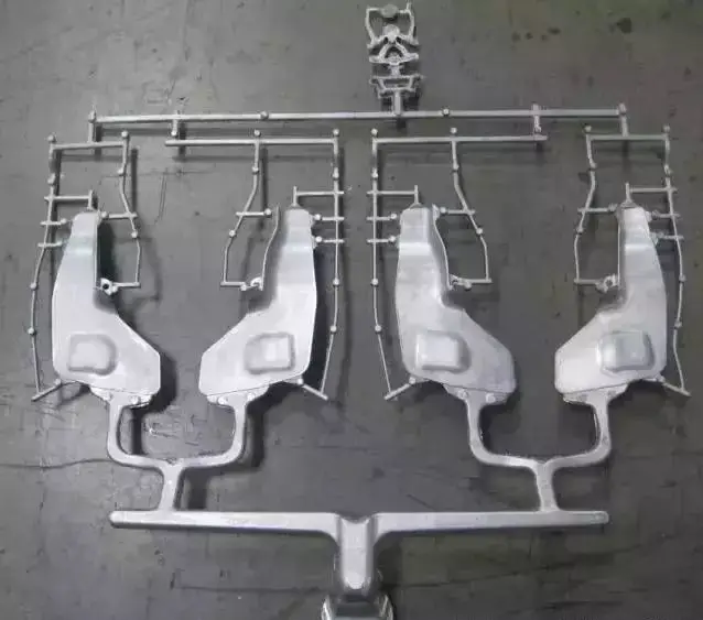
1. Gate location requirements
1. Appearance requirements (gate marks, weld lines)
2. Product functional requirements
3. Mold processing requirements
4. Warp deformation of the product
5. The gate is not easy to remove
2. Impact on production and functions
1. Flow Length determines the injection pressure, clamping force, and whether the product is filled or not. Shortening the full flow length can reduce the injection pressure and clamping force.
2. The gate position will affect the holding pressure, the size of the holding pressure, and whether the holding pressure is balanced. Keep the gate away from the future stress position of the product (such as the bearing) to avoid residual stress. The gate position must consider exhaust to ensure To avoid wind accumulation, do not place the gate in a weak or embedded part of the product to avoid core Shaft.
3. Tips for selecting gate location
3. Tips for selecting gate location
1. Place the gate at the thickest part of the product. Pouring from the thickest part can provide better filling and pressure-holding effects. If the holding pressure is insufficient, thinner areas will solidify faster than thicker areas. Avoid placing the gate where the thickness suddenly changes to avoid hysteresis or short shots.
2. If possible, pour from the center of the product. Placing the gate in the center of the product can provide equal flow lengths. The size of the flow length will affect the required injection pressure. Central pouring makes the holding pressure uniform in all directions. Uneven volume shrinkage can be avoided.
3. Gate: The gate is a short groove with a small cross-sectional area, used to connect the runner and the mold cavity. The cross-sectional area should be small in order to achieve the following effects:
1) Soon after the mold cavity is injected, the gate becomes cold.
2) The water removal port is simple.
3) The water outlet is removed, leaving only a few traces
4) Make the filling of multiple mold cavities easier to control.
5) Reduce the phenomenon of excessive filler.
There are no hard and fast rules for designing gates. Most of them are based on experience, but there are two basic factors that must be compromised:
1. The larger the cross-sectional area of the gate, the better, and the shorter the length of the channel, the better, to reduce the pressure loss when the plastic passes through.
2. The gate must be narrow to facilitate cold freezing and prevent excessive plastic from flowing back. Therefore, the gate should be in the center of the runner, and its cross-section should be as circular as possible. However, the gate switch is usually made of a module Determined by the switch.
3. Gate size: The size of the gate can be determined by the cross-sectional area and gate length. The following factors can determine the optimal size of the gate:
3. Gate size: The size of the gate can be determined by the cross-sectional area and gate length. The following factors can determine the optimal size of the gate:
1) Rubber flow characteristics
2) Thickness of the module
3) The amount of glue injected into the mold cavity
4) Melting temperature
5) Work mold temperature
When deciding the location of the gate, the following principles should be adhered to:
1. The amount of rubber injected into each part of the mold cavity should be as even as possible.
2. The rubber injected into the mold should maintain a uniform and stable flow front at each stage of the injection process.
3. Consideration should be given to the possible occurrence of weld marks, bubbles, pits, empty positions, insufficient glue injection and glue spraying.
4. The operation of the water removal outlet should be made as easy as possible, preferably automatic operation.
5. The location of the gate should cooperate with all aspects.
4. Gate balance
If a balanced runner system cannot be obtained, the following gate balancing method can be used to achieve the goal of uniform injection molding. This method is suitable for molds with a large number of mold cavities.
There are two gate balancing methods:
There are two gate balancing methods:
Change the length of the gate channel and change the cross-sectional area of the gate. In another case, that is, when the mold cavity has different projected areas, the gate also needs to be balanced. At this time, to determine the size of the gate, you must first determine the size of one of the gates and find its corresponding The ratio of the mold cavity volumes, and by applying this ratio to the comparison between the gate and each corresponding mold cavity, the size of each gate can be obtained successively. After the actual test casting, the balance of the gate can be completed operate.
5. The location of the gate in the runner
When the plastic flows into the flow channel, the plastic close to the mold surface first loses heat (cools) and solidifies. When the plastic flows forward, it only flows through the plastic layer solidified here. And because plastic is a low heat transfer material, solid plastic forms The green insulation layer and the holding layer can still flow. Therefore, ideally, the gate should be set at the cross-runner layer to achieve the best plastic flow effect. This situation is most common in circular and hexagonal cross-runners. .However, the trapezoidal cross-flow channel cannot achieve this effect because the gate cannot be placed in the middle of the flow channel.
6. Direct Gate or SprueGate
The sprue directly supplies plastic to the finished product. The sprue is adhered to the finished product. In a two-plate mold, the large nozzle is usually one outlet, but in the design of a three-plate mold or hot runner mold, it can be one Lots of beer.
Disadvantages: The formation of water mark on the surface of the finished product will affect the appearance of the finished product. The size of the water mark depends on the small diameter hole of the nozzle.
7. The demoulding angle of the nozzle and the length of the nozzle
Therefore, the large nozzle mark can be thinned by changing the size of the nozzle to a smaller size. However, the diameter of the nozzle is affected by the diameter of the nozzle, and since the nozzle must be easy to release from the mold, the demoulding angle cannot be less than 3 degrees. Therefore, Only the length of the nozzle can be shortened by lengthening the nozzle.
Gate selection: The gate is the connection part between the runner and the cavity, and is also the last part of the injection mold feeding system. Its basic functions are:
1) Make the molten plastic from the runner enter the filling cavity as quickly as possible.
2) After the mold cavity is filled, the gate can be quickly cooled and sealed to prevent the uncooled plastic from flowing back into the cavity.
Summary: The design of the gate is related to factors such as the size and shape of the plastic part, the mold structure, the injection process conditions and the performance of the plastic part. However, according to the basic functions of the above two sentences, the gate section should be small and the length should be short, because only in this way can the gate It meets the requirements of increasing the flow rate, rapid cooling and sealing, easy separation of plastic parts and minimal gate marks.
The key points of gate design can be summarized as follows:
The key points of gate design can be summarized as follows:
1. The gate is opened in the thicker section of the plastic part to allow the molten material to flow from the thick section into the thin section to ensure complete mold filling;
2. The gate location should be selected to minimize the plastic filling process to reduce pressure loss;
3. The selection of the gate location should be conducive to eliminating air in the cavity;
4. The gate should not allow the molten material to rush directly into the mold cavity, otherwise it will produce swirling flow and leave spiral marks on the plastic parts. This defect is especially likely to occur with narrow gates;
5. The location of the gate should be selected to prevent stitching lines on the plastic surface. Especially in ring or cylindrical plastic parts, the gate should be located
Are you looking for precision-engineered components that meet your exact specifications? Look no further! Our CNC machining services offer top-notch precision and reliability for all your turning needs.
Analysis of the development status of aluminum alloy die-casting process and mold technology
Related Article
Fast sampling is the fastest way to win business in the hardware machining and plastic mold industries. Customers want a working sample in days, and a 3D printer delivers it, but only when you know how to print in 3d correctly.
how to print in 3d
Fast sampling is the fastest way to win business in the hardware machining and plastic mold industries. Customers often send an STL file and expect a working sample in days.
how to print an stl file