INJECTION MOLD DESIGN Of HIGH-POWER LASER EQUIPMENT BOTTOM CASE + 3D
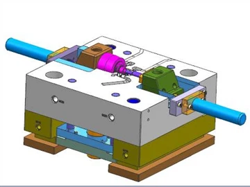
The bottom shell products of high-power laser equipment are shown in Figure 1. The maximum dimensions of the product are 594.95 mm x 330.50 mm x 150.45 mm; the average thickness of the plastic part is 4.00 mm, the material of the plastic part is ABS + PC, the shrinkage rate is 1.005, and the weight of the plastic part is 3256.94 grams. The technical requirements for plastic parts are that there should be no defects such as peaking, injection dissatisfaction, flow lines, pores, warping deformation, silver streaks, cold material, and spray lines.
Figure 1 High-power laser equipment bottom shell product map
It can be seen from Figure 1 that the plastic part is a large plastic part, and the mold must be a large mold. According to the analysis of the structure of the plastic part, large sliders need to be designed on both short sides. Large sliders also need to be designed on both sides. The difficulty in mold design is that the slider on one side of the long side is inclined, and the rear mold needs to be designed to tilt the slider. Another difficulty is the design of the parting surface at the junction between the sliders, that is, the sliders on the two short sides need to turn to wrap the plastic part. , see 3D diagram. Another characteristic of plastic parts is that there are many local sinking glue positions, the sinking depth of the glue position is very large, local heat is concentrated, and it is easy to cause insufficient cooling, which affects the quality of plastic parts and the injection molding cycle.
The size of the plastic part is large and requires a lot of rubber. The mold design cavity is 1 out of 1. The mold base is a non-standard mold base 85120, and the mold base is a straight mold base. The gating system design adopts the direct large nozzle design of the main channel for glue feeding, which is conducive to the rapid filling of molten plastic. The two sliders on the sky and earth side are arranged obliquely in the horizontal plane, as shown in Figure 6.
The slider core-pulling force of the large mold is large, and the three sliders are all driven by oil cylinders.
The characteristics of hydraulic core pulling are: since the force point of the core pulling is set at the center of the side pulling force, and it is a linear translational motion, the movement is stable when the core is pulled. At the same time, the pulling force and the core-pulling distance can be set very large, and the mold structure is relatively simple, which is easy to manufacture, so the cylinder core-pulling is widely used in the mold. Its disadvantage is that it needs a whole set of hydraulic devices, and the mold occupies a large space. Because of the cumbersome work control and the impact on the injection molding cycle, it is limited in application. For German customers, they always prefer mechanical drive core pulling rather than oil cylinder core pulling. Therefore, the use of oil cylinder core pulling for export molds must be confirmed by the customer.
When using oil cylinders for export molds, you need to pay attention to the customer's requirements for the oil cylinder brand. North American customers mostly use PARKER oil cylinders or MILLER oil cylinders; German customers like Merkel oil cylinders; Japanese customers like Sun Iron oil cylinders; Taiwan has Junfan oil cylinders.
When the stroke of the slider is large or the slider of the movable mold is inclined to the side of the movable mold, if the inclined guide column is used to pull the core, the force will be poor and it will be easily damaged; therefore, when the stroke of the slider exceeds 60, the core should be pulled with an oil cylinder , can effectively improve the stress condition.
The maximum working pressure of PARKER cylinder usually has three types: 7MPa, 14MPa and 21MPa. In mold design, two types of 7MPa and 14MPa are usually used. Generally, the driving force of the oil cylinder is not calculated during the mold design. However, if there is no analog object or when the slider is particularly large or the stroke is particularly long, the driving force of the cylinder must be calculated in order to select a suitable cylinder.
Figure 2 3D drawing of mold design
Figure 3 Die parting surface diagram
Figure 4 Tilt slider design
The structure of an inclined slider is shown in Figure 4. Because a plurality of small inclined holes are inclined to the back mold, therefore, the slide block will also be inclined to the back mold. The mold structure is that the B plate is separated from the backing plate by 40mm, the inclined guide column is fixed on the backing plate, and the slider slides obliquely on the B plate. Use the buckle to control the separation of the templates, as shown in Figure 5. The buckle machine is installed on the ejector plate, and the B plate is separated from the backing plate when it is ejected, so as to realize inclined core pulling.
Since there are many sunken closed structures of plastic parts, the heat is not easy to discharge. Beryllium copper is used to make inserts at the sunken glue position. On the one hand, the cooling effect of beryllium copper is better, on the other hand, the release effect of beryllium copper is also very good, which can effectively reduce the clamping force. Both the front and rear molds are designed with a pond circuit for cooling, and the cooling water path is connected to the beryllium copper to better exert the cooling performance of the beryllium copper. The slider is also designed with a straight-through water delivery to ensure that the injection molding can be carried out normally.
Figure 5 Analysis of mold opening action
Figure 6 Plane view of the rear mold
Casting Process Design And Trial Production Of Aluminum Alloy Pressure Shell Castings
Domestic Patent: An Extrusion Casting Method For The Metal Mold Of The Main Body Of The Aluminum Alloy Suspension Clamp
Related Article