Solve The Vibration Pattern Of The Lathe, Find The Root Of The Problem, And Make The Product Shine in One Step
2023-04-28

During lathe machining, the parts appear vibration patterns. It is estimated that friends who are dry machine machining have encountered it more or less. This situation can be said to be everywhere in the factory.
I believe that you will often encounter it when you are doing a fine car. The car does not have a beautiful appearance. It needs to be lightly polished with fine sandpaper or oil stone. Especially after electroplating is required for high precision, you need to be very careful at this time, otherwise it will easily become a waste product.
Because there are too many factors that can cause vibration patterns in the product, we can start to investigate from these aspects first, and analyze in detail according to our own factory conditions.
First of all, judge whether there is "vibration pattern". The usual rule is: there is a horizontal pattern, as shown in the figure, it looks like a spiral pattern with a relatively large spacing.
1. It is necessary to know whether the workpiece has vibration marks after one-time machining, or whether it has vibration marks after secondary finishing.
2. Is the machine collided with the machine? If it collides with the machine, it is easy to have the effect of the Z-axis screw and the spindle, and vibration patterns will appear in this case.
3. See if the speed of the machine tool is within a reasonable range, and at the same time change the feed from rotation to sub-feed in the sequence to try. (The rotational speed of the machine tool is resolutely high, resulting in uneven feed speed, acceleration and deceleration from time to time, and if the precision of the machine tool unit and the actuator is not high enough, it is easy to form ripples)
The display on the panel of ordinary machine tools is the speed reflected by the actual spindle encoder. Check whether the speed is stable during the task. The most direct way is to directly change the rotation feed to the component feed. If the effect is improved, then it is normal. It is an encoder defect or a frequency converter defect.
4. The rigidity of the drive of the machining center system does not match
5. The fixed rigidity of the workpiece itself or the workpiece, such as some smaller and thinner parts due to their own lack of rigidity, or due to the shape of the workpiece, it is impossible to use a reasonable press-fitting fixture for sufficient fixation.
6. The Z-axis screw rod supports the bearing, and the loose back cap can easily cause vibration marks.
7. The knife has no effect, whether the arc of the knife tip is too large, and the blade is too wide to easily appear horizontal lines. Directly change hands to sharpen the knife, which can reduce vibration, or the knife tip can grind out a transitional blade.
8. The rigidity and dynamic balance of external reasons are relative to the rotation axis, and the mass imbalance caused by external factors will cause vibration marks due to the unbalanced centripetal force during rotation. Especially in high-speed processing, the dynamic balance of the tool has a great influence.
9. The selection of cutting parameters includes cutting speed, feed, feed amount and cooling method, etc.
10. The guide rail of the machining center machine tool is loose
In fact, the appearance of adding vibration lines should be avoided from the source, and try to avoid vibration when cutting the workpiece.
Mastering the Injection Moulding Process Step by Step
Casting Process Design And Trial Production Of Aluminum Alloy Pressure Shell Castings
Related Article
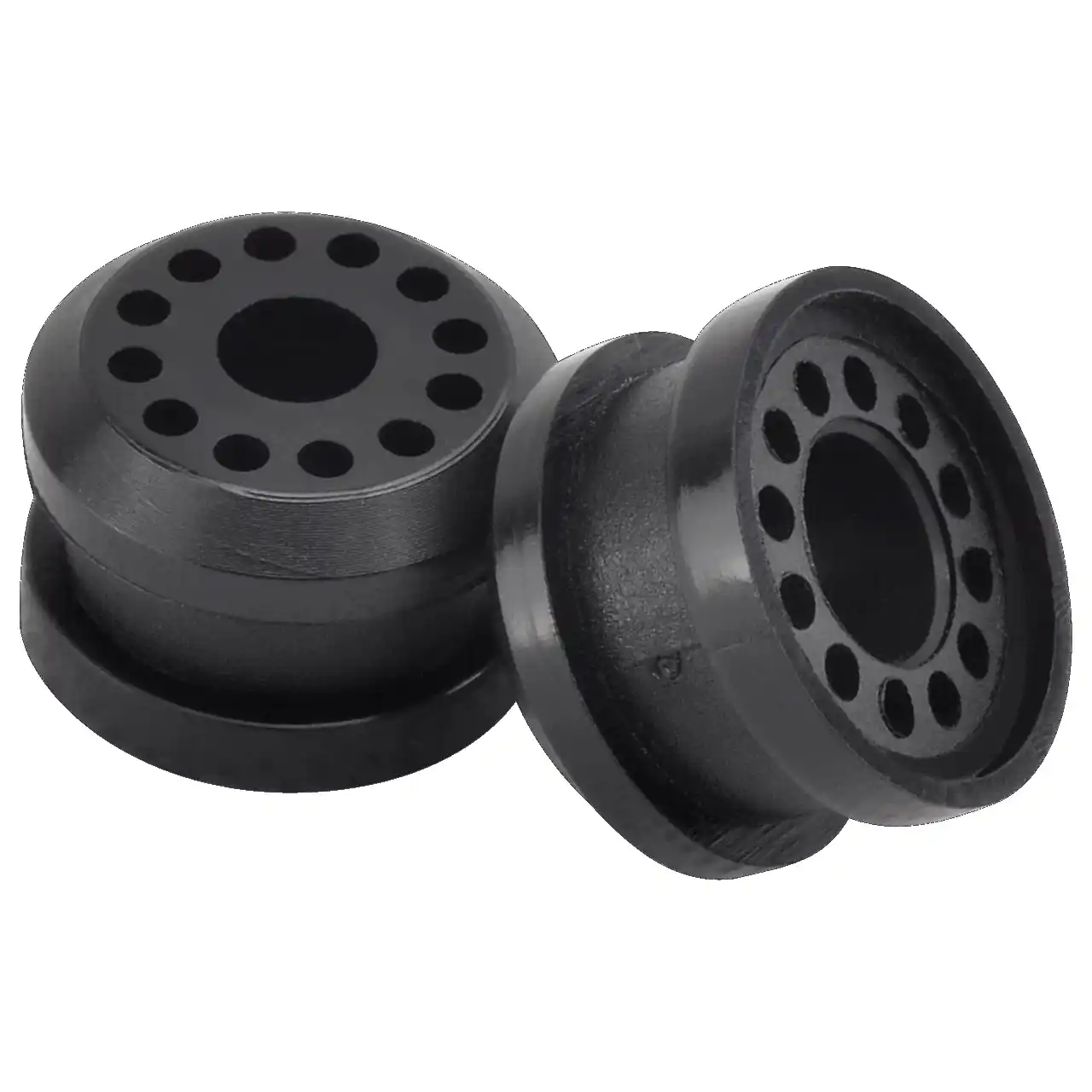
Fast sampling is the fastest way to win business in the hardware machining and plastic mold industries. Customers want a working sample in days, and a 3D printer delivers it, but only when you know how to print in 3d correctly.
how to print in 3d
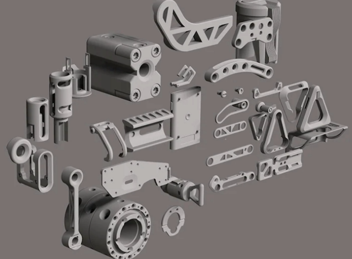
Fast sampling is the fastest way to win business in the hardware machining and plastic mold industries. Customers often send an STL file and expect a working sample in days.
how to print an stl file