Key points of injection mold design for imager inner bracket and 3D drawing
2023-06-27
Proper mold design is vital for quality imager inner brackets. This article discusses the importance of mold design and its relation to product quality and efficiency. The mold design process, including computer-aided design and manufacturing, is examined. The article also covers the types of materials and manufacturing techniques used in mold design for imager inner brackets. Optimizing the mold design process can lead to reduced production time and cost, as well as improved product quality. Ensure your image inn
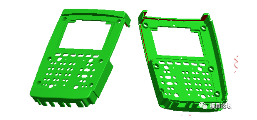
Figure 1 Product picture of the inner bracket of the imager
The imager inner bracket products are shown in
Figure 1. The maximum dimensions of the product are 213.00 mm x 148.95 mm x 29.70 mm; the average thickness of the plastic part is 3.00 mm, the material of the plastic part is ABS, the shrinkage rate is 1.005, and the weight of the plastic part is 92.46 grams. The technical requirements for plastic parts are that there should be no defects such as peaking, injection dissatisfaction, flow lines, pores, warping deformation, silver streaks, cold material, and jetting lines, and meet ROSH environmental protection requirements.
Figure 1 Product picture of the inner bracket of the imager
It can be seen from Figure 1 that the plastic part is a flat shell. The size of the plastic part is large, there is a gap on the edge, there is a large square hole on the top surface, and there are also many small round holes and small square holes. The key points of mold design for plastic parts with multiple holes on the top surface were introduced in the previous article on electronic calculator surface shell mold design. Plastic parts with this structure will make the flow of molten plastic difficult, and glue lines will be formed on the edge of each hole, and the shrinkage rate of the plastic parts will also decrease accordingly. The sides of both ends of the plastic part are zero-degree vertical planes, and the slider core must be designed. This zero-degree vertical surface cannot be designed with a demoulding slope, nor can it be suggested to the customer to make a demoulding slope. Because the zero-degree vertical surface here is a surface with functional requirements, not just an appearance surface.
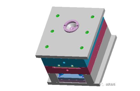
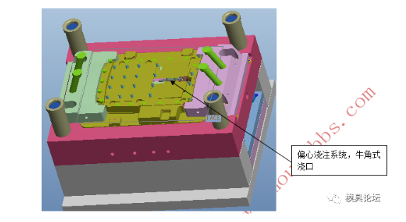
Figure 2 3D drawing of mold
The size of the plastic part is large, and the mold design cavity is 1 out of 1. The 3D view of the mold is shown in Figure 2, and the parting surface of the mold is shown in Figure 3. Before the mold design, first analyze the plastic part to check out the impact on the mold quality If necessary, make corresponding technical documents and submit them to customers for confirmation. At present, the common practice is to carry out the ranking work of the mold design before the mold manufacturing and processing. Through the inspection of the ranking, hidden dangers can be eliminated, the number of rework and trial molds can be reduced, the quality of the molded plastic products can be guaranteed, the cost can be reduced, and the optimization can be optimized. The overall design of the mold.
Figure 3 Die parting surface diagram
Figure 4 3D diagram of the rear mold core
Design for Manufacturing (DFM for short) is to study the interrelationship between design and manufacturing. Integrating the manufacturing system into the mold design for overall optimization is an indispensable work to improve the quality and efficiency of placement, and generally serves as an important basis for mold quotations. Mold DFM is an important part of concurrent design. Its purpose is to consider manufacturing-related issues in the early stage of design, so as to reduce and find design errors as early as possible, shorten the mold development cycle, and reduce costs. In the DFM of the mold factory, designers need to consider various factors in the mold manufacturing process, generally including product material, shrinkage rate, number of mold cavities, pouring system, insert division and parting line, ejector mechanism type and position, As well as the form of core pulling or inclined top, whether the product has sufficient demoulding slope, whether there is an undercut affecting the molding, etc.
In order to fully understand the mold process performance and molding requirements of the customer's products, the following issues must be understood during the process review of the product drawing, mainly referring to the problems that affect the appearance of the product, and also directly affect the mold structure plan. Therefore, it must be with Customer communication, understand customer requirements and get customer approval.
1 The shape and position of the parting line PL and the penetration position of the through hole;
2 The gate position, gate quantity and gate size allowed by the product and the weld line (grain) position and quantity allowed by the product;
3 Front and rear mouldings, traces of stitching lines and sliders; the edge of the rear mold core formed by the seam of the edge of the plastic part is raised, which can be directly processed by CNC, and it is not necessary to make an insert. If it is concave, it must be cut. See Figure 4.
4. Front and rear mold insert thread traces and step difference;
5 Are the wall thickness, rib thickness, column thickness, etc. reasonable? Is the wall thickness at the root of all ribs, columns, etc. 0.6 times that of the top? What changes can be made?
6 Front and rear mold drafting angles, etch number and lettering content, height, position and other dimensions;
7 The size and direction of the basic demoulding slope where the demoulding slope is not noted;
8 For the injection molding material and color of the product (dark or transparent, brown), is it allowed to leave traces such as push rods, push blocks, sliders, and inclined tops?
9 Is there any glue position interference in the direction of movement of the slider and the inclined top? What to do?
10 Contents and positions of signs such as embossed characters, symbols, dates, and material names on the product;
11 When one mold has multiple cavities, the positions of the mold cavity numbers (1, 2, 3, ...) should be arranged in order;
12 When the mold has many inserts, it is necessary to mark the same number on the bottom of the insert and the insert hole of the inner mold to ensure one-to-one correspondence;
13 Fillet processing (process fillet, absolute sharp corner, inlay, original processing fillet, and whether to cancel the fillet);
14 Strength and stiffness of the slender core;
15 Metal insert loading method (embedding before injection molding or hot pressing after injection molding, etc.);
16 Accuracy requirements such as dimensional tolerance and geometric tolerance, surface treatment (engraving, etching, mirror surface...);
17 The surface treatment method of the product after injection molding (oil injection, electroplating...), the electroplating parts must have a flow channel connection;
18 Solution to product deformation;
19 Is the product to be machined after injection molding? Such as: gate removal, drilling, etc.
20 The assembly structure of each plastic part in this project: whether there is a gap between the matching parts, and whether there is an aesthetic line between the cooperation of the appearance parts (to prevent misalignment and hide the ugliness);
The core-pulling mechanisms of the two sliders all use inclined guide pillars for core-pulling, which is stable and reliable. The ejection adopts dome needle ejection.
er brackets are designed with the highest level of performance by using the right mold design techniques and materials.There are many types of five-axis machine tools, do you know all of them?
What material is 5% as dense as steel but 10 times stronger?
Related Article
Fast sampling is the fastest way to win business in the hardware machining and plastic mold industries.
how to print things

Fast sampling is the fastest way to win business in the hardware machining and plastic mold industries.
how to print on a 3d printer