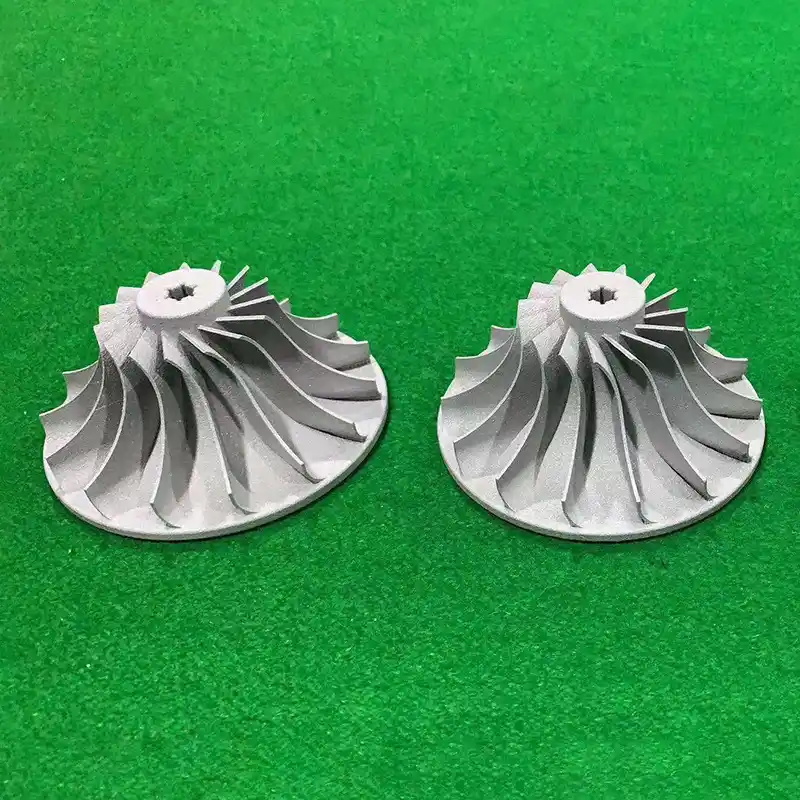
How to 3D Print Design: Complete Guide for Hardware and Plastic Mold Rapid Sampling
Author: SZTC
2026-09-21
In modern hardware processing and plastic mold manufacturing, 3D printing design has become the core skill of rapid prototyping. Unlike traditional CNC machining and injection molding design, 3D print design follows additive manufacturing logic, focusing on layer stacking feasibility, structural stability and process adaptability. Most factory engineers encounter repeated printing failures, dimensional errors and weak prototype strength simply because they apply traditional machining design standards to 3D printing projects. For mold inserts, custom hardware fixtures and functional test samples, every designer must master one core skill: how to 3D print design that fits industrial rapid sampling standards. This article delivers a full-process, industry-specific design guide to help factories achieve high-precision, low-cost and high-yield 3D printing samples.
1. Understand Core Differences: 3D Print Design vs Traditional Industrial Design
To truly master how to 3D print design for mold and hardware production, designers must abandon subtractive manufacturing thinking and rebuild design logic for additive processes. Traditional design pursues machining convenience, while 3D print design prioritizes printing feasibility, structural performance and post-processing efficiency.
1.1 Process-Oriented Design Logic Shift
Traditional hardware and mold design allows ultra-thin residual walls, deep blind holes and complex undercut structures, which can be realized through cutting and grinding. In contrast, 3D printing relies on layer-by-layer material stacking, so unreasonable thin walls, sharp overhangs and unclosed meshes will directly cause printing collapse, warping and layer separation. Qualified 3D print design must balance industrial functionality and printing process characteristics to ensure every structure is printable and stable.
1.2 Industrial Standard Requirements for Rapid Sampling
Different from consumer-grade 3D printing design, mold and hardware sample design requires strict dimensional tolerance, assembly accuracy and mechanical strength. The design needs to simulate actual injection molding effects for plastic mold samples and meet load-bearing and wear-resistant standards for hardware functional prototypes. Only process-optimized design can guarantee that printed samples support formal structural verification, assembly testing and mold flow simulation.
2. Basic Design Rules: Foundation of Qualified 3D Print Design
All industrial rapid sampling projects follow unified basic design principles. Mastering these standards is the first step to answer how to 3D print design efficiently and avoid basic printing failures.
2.1 Standardized Minimum Wall Thickness Setting
Wall thickness determines the structural stability and printing success rate of mold and hardware samples, and different printing processes have fixed safe thresholds. For FDM-printed hardware jigs and structural brackets, the minimum wall thickness should be controlled above 1.2mm to prevent layer cracking and deformation. For SLA high-precision plastic mold cavity samples, the safe wall thickness is 0.8mm or higher to restore fine surface textures. For metal 3D printed mold inserts and high-strength hardware parts, the wall thickness must exceed 1.0mm to ensure dense internal structure and uniform stress distribution. Sudden thickness transitions should be avoided to prevent differential cooling and residual warping.
2.2 45-Degree Overhang Self-Support Rule
Excessive overhanging structures require a large number of auxiliary supports, which increase material costs, prolong printing time and leave support marks on key assembly surfaces. The core 3D print design standard is the 45-degree self-support rule. Structures with an inclination angle above 45 degrees can realize self-support stacking without auxiliary structures. For overhangs below 45 degrees, designers need to optimize structural angles, add chamfers or adjust modeling layouts to minimize redundant supports, especially for precision mold texture surfaces and hardware matching planes.
2.3 Closed Watertight Model Structure
A printable 3D model must be a completely watertight manifold structure with no open edges, tiny gaps or overlapping surfaces. Non-closed models cannot be recognized normally by slicing software, resulting in printing interruption and structural defects. In mold and hardware design, tiny mesh errors often appear at threaded holes, chamfer transitions and thin-wall joints. Designers must conduct strict mesh inspection and repair to ensure the integrity of the overall model structure before printing.
3. Scenario-Based Optimization: 3D Print Design for Mold and Hardware Sampling
Plastic mold samples and hardware functional parts have completely different usage scenarios and performance requirements. Targeted design optimization is the key advanced skill of how to 3D print design for industrial rapid sampling.
3.1 Plastic Mold Sample Design Optimization
The core goal of mold sample printing is to verify cavity structure, demolding performance and mold flow rationality. In design, add standard draft angles to vertical mold walls to simulate real injection demolding effects and avoid undercut structures that affect mold trial results. For conformal cooling channels, optimize hollow pipeline structures to ensure smooth stacking and unobstructed internal channels, providing accurate data for subsequent formal mold processing. Meanwhile, simplify non-key decorative structures and focus on retaining functional features to improve printing efficiency and reduce sampling costs.
3.2 Hardware Functional Prototype Design Optimization
Hardware samples focus on assembly accuracy and mechanical performance. In the design stage, replace sharp right-angle structures with rounded transitions to reduce stress concentration and prevent structural fracture during strength testing. Strengthen the wall thickness of load-bearing connection parts and optimize hole position tolerance. Since 3D printed holes will shrink slightly during cooling, designers need to oversize the hole diameter by 0.1mm to 0.2mm in advance to ensure precise assembly and matching. For movable hardware parts, appropriately reduce internal infill density under the premise of ensuring strength to reduce weight and printing time.
4. Post-Design Calibration and Printing Parameter Matching
Excellent design needs to match reasonable printing parameters to exert maximum effect. Standardized calibration processes avoid design waste and ensure sample consistency.
4.1 Model Orientation Optimization
Printing orientation directly affects surface quality and structural strength. For mold cavity samples with high surface requirements, place the key texture face upward to avoid layer line marks on the build plate. For load-bearing hardware parts, arrange the stacking direction consistent with the stress direction to improve overall tensile and bending resistance. Reasonable orientation can greatly reduce post-polishing workload and improve sample qualification rate.
4.2 Material Adaptation Design Adjustment
Different printing materials have different shrinkage rates and hardness characteristics, requiring targeted design adjustment. High-temperature resin materials have low shrinkage and are suitable for fine mold samples; nylon materials have good toughness and need proper structural optimization for wearable hardware parts; metal powders have high density, so thin-wall structures need enhanced reinforcement. Designers must adjust structural details according to material characteristics to avoid deformation and performance defects.
4.3 Slicing and Tolerance Secondary Confirmation
After design completion, import the model into slicing software for preview inspection, check for unprintable areas and unreasonable support layouts, and fine-tune local structures. For high-precision industrial samples, confirm dimensional tolerance data again to ensure the printed prototype fully meets factory assembly and testing standards.
5. Common 3D Print Design Mistakes to Avoid
Most sampling failures in mold and hardware workshops come from universal design errors. Avoiding these problems can effectively improve printing efficiency and reduce repeated iteration costs.
5.1 Directly Using Traditional Machining Models
Models designed for CNC machining usually contain ultra-thin walls, unclosed gaps and unreasonable undercut structures, which cannot be directly used for 3D printing. Blind use will lead to collapse, warping and unqualified samples, delaying project progress.
5.2 Excessive Complexity of Redundant Structures
Overly complex nested structures and tiny unnecessary details increase printing difficulty and failure risks. For rapid sampling that only verifies core functions, properly simplifying non-key structures can balance sample quality and production cost.
5.3 Ignoring Post-Processing Feasibility
Design should reserve operating space for post-processing such as support removal, polishing and assembly. Too narrow internal spaces and fully enclosed complex structures will lead to difficult post-processing, affecting the final delivery quality of industrial samples.
6. Conclusion
In conclusion, the core solution to how to 3D print design for hardware and plastic mold rapid sampling is to establish additive manufacturing-oriented design standards. Qualified industrial 3D print design needs to comply with standardized wall thickness and overhang rules, adopt scenario-based structural optimization, and complete material adaptation and orientation calibration. Scientific design not only effectively reduces printing failure rates and iteration costs, but also ensures that each prototype can accurately simulate mass production performance. For modern mold and hardware processing enterprises, proficient 3D print design capabilities are essential to improve rapid sampling efficiency, shorten product R&D cycles and enhance market competitiveness.


Samuel Song Your service representative
samuel@chnzhongzhu.com WhatsApp:+86 18688963321
Specializing in zinc-aluminum-magnesium alloy die-casting processing, CNC milling, CNC turning, 3D printing, injection molding and sheet metal processing. Manufacturing services.
How to 3D Print for Beginners | Step-by-Step Guide for Mold & Hardware Sampling
How to 3D Model for 3D Printing | Complete Guide for Mold & Hardware Sampling
Related Article
Machine parts are essential crafting materials in Fortnite: Save the World. They are used to craft weapons and traps, so running short can slow down mission progress.
how to collect machine parts in save the world?
In hardware machining and plastic mold manufacturing, machines use rotating, cutting, pressing, and moving components to shape materials. These parts can create serious hazards if workers come into contact with them during operation.
which of the following machine parts always require guards?