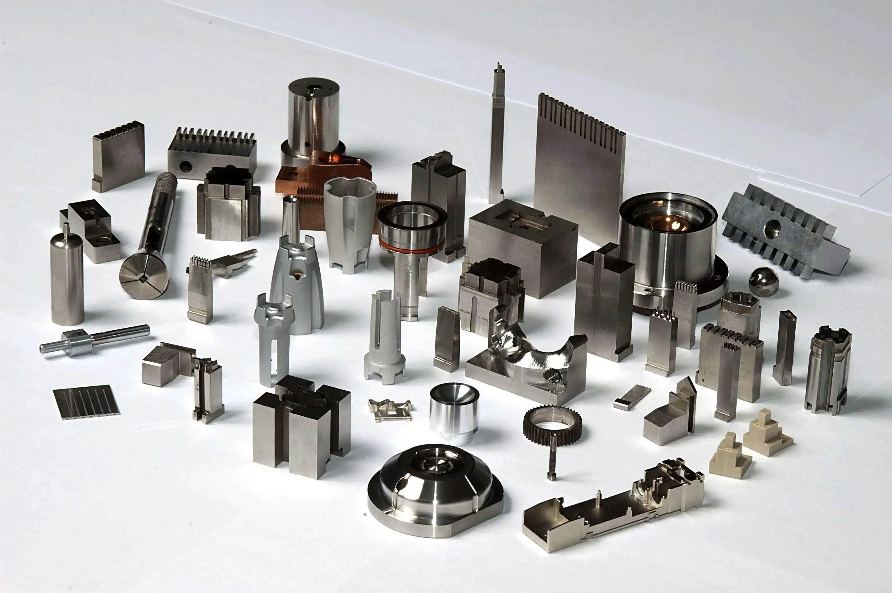
How to Create STL Files: Industrial Step-by-Step Guide for Hardware & Mold Rapid Sampling
Author: SZTC
2026-10-08
In the plastic mold and hardware processing industries, STL files serve as the universal bridge between 3D design and physical rapid sampling. Almost all industrial 3D printers, including FDM, SLA, and metal printing devices, rely on STL files to generate slicing paths and complete layer-by-layer manufacturing. Most workshop printing defects, such as surface faceting, dimensional deviation, hollow structures, and printing crashes, stem from improperly created STL files rather than printer or material issues. For industrial designers and prototype technicians focusing on fast, low-cost mold and hardware verification, the core operational question is straightforward: how to create STL files that meet industrial precision standards for reliable rapid sampling. This article shares a complete factory-grade STL creation workflow tailored for mold cavity prototypes and hardware functional parts.
1. Understand Industrial STL File Basics
Before mastering specific creation steps, it is necessary to clarify the industrial attributes of STL files, which lays the foundation for learning how to create STL files for qualified manufacturing prototypes.
1.1 What Is an Industrial-Grade STL File
STL (Standard Tessellation Language) is a universal 3D file format that converts parametric CAD models into triangular mesh surfaces. Unlike original STEP or IGES design files, STL files do not store design parameters, historical features, or curve data. They only record spatial coordinate information of model surfaces, ensuring full compatibility with all industrial slicing software and printing equipment. For mold and hardware rapid sampling, qualified STL files must feature watertight geometry, uniform mesh distribution, and no structural defects to support stable additive manufacturing.
1.2 Differences Between Hobby and Industrial STL Files
Consumer-grade STL files only require complete appearance modeling for decorative printing. In contrast, industrial STL files for mold and hardware sampling demand strict precision standards. High-quality industrial STL files maintain smooth mesh transitions on mold curved surfaces, consistent wall thickness for hardware load-bearing structures, and accurate dimensional tolerance for assembly features. Low-quality STL files with rough meshes, missing faces, or distorted triangles will cause layer lines, structural collapse, and unqualified assembly effects in industrial sampling.
1.3 Why STL Files Dominate Industrial Rapid Sampling
STL format occupies a dominant position in mold and hardware prototyping due to its excellent compatibility, lightweight file size, and easy repairability. It supports one-click conversion from all mainstream industrial CAD software and adapts to plastic, resin, and metal printing processes. Compared with other formats, STL files simplify model transmission, slicing processing, and batch printing management, perfectly matching the efficient iteration rhythm of factory rapid sampling projects.
2. Prepare CAD Models for STL Conversion
High-quality STL files originate from standardized CAD models. Pre-conversion optimization is the key preliminary step to solve how to create STL files with zero defects.
2.1 Eliminate Non-Printable Structural Defects
Most original CAD models are designed for CNC machining or injection molding, containing unprintable features that affect STL quality. Before conversion, remove ultra-thin walls, tiny blind holes, redundant internal faces, and unreasonable undercut structures. Optimize abrupt thickness transitions and sharp right angles to avoid mesh distortion during STL tessellation. Retain core functional features such as mold cavity textures, cooling channels, and hardware assembly holes to ensure sampling authenticity.
2.2 Unify Dimensions and Unit Standards
STL files do not carry unit information, making unit confusion a common industrial error. Uniformly set all mold and hardware model units to millimeters before export. Calibrate overall dimensions and key tolerance positions to avoid size deviation caused by inch-millimeter conversion errors. Confirm symmetrical structures and hole position accuracy to ensure the final printed sample matches design specifications.
2.3 Optimize Model Printability
Follow DfAM (Design for Additive Manufacturing) rules to optimize models. Set industrial standard wall thickness: 0.8mm minimum for SLA mold samples and 1.2mm for FDM hardware parts. Add rounded fillets to stress concentration areas and adjust overhang angles to reduce support dependence. Reasonable structural optimization ensures the converted STL file has excellent printability and stable molding performance.
3. Step-by-Step Workflow: How to Create STL Files
This standardized industrial process fully answers how to create STL files, covering CAD export, parameter setting, mesh inspection, and defect repair for mold and hardware scenarios.
3.1 Select Professional Creation Tools
Match tools according to project precision requirements. For high-precision mold cavity models and complex hardware structural parts, use industrial parametric software including SolidWorks, UG NX, and Fusion 360. For simple fixture prototypes and basic structural verification, free tools such as FreeCAD and Tinkercad can complete qualified STL creation. Professional tools ensure uniform mesh density and precise feature restoration for industrial sampling standards.
3.2 Set Critical STL Export Parameters
Export parameters directly determine STL file quality. The core parameters include chord height (deviation tolerance) and angle tolerance. For high-precision plastic mold samples with curved surfaces and fine textures, set the chord height between 0.02mm and 0.05mm to restore smooth surface details and avoid obvious faceting. For ordinary hardware structural parts, set a moderate tolerance to balance file size and printing precision. Always choose binary STL format instead of ASCII format for smaller file size, faster slicing speed, and more stable data transmission.
3.3 Complete Standard CAD-to-STL Export
After parameter confirmation, select the target model and perform one-click export. Check the “selected object only” option to avoid importing redundant background structures. For multi-part combined molds and hardware assemblies, export separately according to single printing units to prevent mesh confusion and structural overlapping. Save files with standardized project naming for convenient batch management and version iteration.
3.4 Inspect and Repair Mesh Defects
Original exported STL files inevitably contain tiny defects such as open edges, non-watertight gaps, flipped normals, and overlapping meshes. Import files into professional mesh repair tools for full inspection. Repair broken surfaces, close tiny gaps, delete redundant internal meshes, and ensure the model forms a completely watertight manifold structure. This step eliminates more than 90% of printing failures caused by defective STL files.
3.5 Secondary Optimization for Industrial Scenarios
Perform targeted optimization based on printing processes. For SLA mold samples, smooth rough meshes on cavity surfaces to improve surface simulation effects. For FDM hardware parts, optimize mesh uniformity of load-bearing walls to enhance layer bonding strength. For metal printing mold inserts, simplify overly dense meshes without affecting structural precision to improve printing efficiency.
4. Scenario-Based STL Creation Tips
Different industrial sampling scenarios require differentiated STL creation strategies to maximize sample quality and yield.
4.1 STL Creation for Plastic Mold Samples
Focus on detail retention and surface fineness when creating mold STL files. Adopt high-precision tolerance settings to restore complex curved surfaces, tiny grooves, and texture features. Retain complete draft angles and demolding structures to ensure printed samples can truly simulate injection molding effects. Avoid excessive mesh simplification that leads to lost mold functional details.
4.2 STL Creation for Hardware Functional Parts
Prioritize structural stability and dimensional accuracy for hardware STL files. Ensure uniform wall mesh distribution and precise hole position coordinates. Reserve reasonable tolerance compensation for assembly structures to match actual fitting demands. Properly simplify non-key appearance meshes to reduce file size and accelerate slicing and printing speed for efficient rapid verification.
5. Common STL Creation Mistakes to Avoid
Avoiding typical errors effectively improves industrial sampling efficiency and reduces rework costs.
5.1 Excessively Low Export Precision
Overly loose tolerance settings lead to serious surface faceting and distorted curved surfaces, making mold samples unable to simulate real injection molding effects and hardware parts fail assembly tests.
5.2 Skipping Mesh Inspection and Repair
Unrepaired non-watertight STL files cause slicing failure, local hollowing, and layer dislocation during printing, resulting in sample scrapping and delayed project progress.
5.3 Mixing Machining and Printing Standards
Retaining CNC-specific residual structures and unreasonable thin walls in STL files leads to poor printability, deformation, and structural fracture in industrial rapid sampling.
6. Conclusion
In conclusion, the systematic answer tohow to create STL files for mold and hardware rapid sampling lies in standardized pre-optimization, precise parameter export, strict mesh inspection, and scenario-based secondary tuning. Qualified industrial STL files are not simple converted CAD files, but printable, defect-free, and process-adaptive models that meet additive manufacturing standards. Mastering professional STL creation workflows can effectively reduce printing failure rates, shorten product iteration cycles, and provide reliable digital support for fast mold verification and hardware functional testing, greatly improving the rapid prototyping competitiveness of modern manufacturing enterprises.


Samuel Song Your service representative
samuel@chnzhongzhu.com WhatsApp:+86 18688963321
Specializing in zinc-aluminum-magnesium alloy die-casting processing, CNC milling, CNC turning, 3D printing, injection molding and sheet metal processing. Manufacturing services.
How to Design 3D Print Models: Complete Industrial Guide for Hardware & Mold Fast Sampling
How to Create 3D Print Files: Complete Industrial Workflow for Hardware & Mold Sampling
Related Article
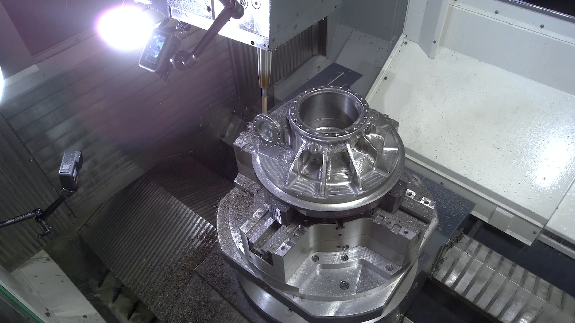
Grinding is not just a finishing touch for auto parts. It is a critical precision machining stage that determines sealing performance, noise level, service life and fatigue resistance of rotating automotive parts.
a grinding machine in an auto parts plant
This guide explains what stresses act on cast iron machine parts, the unique material properties of cast iron, common cast iron grades, CNC machining considerations, failure modes, and how you can evaluate a qualified cast iron machining supplier.
A cast iron machine part is acted upon?
Power transmission is not a single bolt-on component. It forms the motion chain between your prime mover and cutting/feeding units. For machine shops and equipment builders, transmission quality directly determines spindle runout, positioning repeatability and surface finish of machined workpieces.
what part of a machine is the power transmission?