How to 3D Model for 3D Printing | Complete Guide for Mold & Hardware Sampling
Author: SZTC
2026-09-20
In plastic mold and hardware processing industries, 3D printing has become the mainstream solution for rapid prototyping and sample verification. However, many engineers and new workshop staff struggle with a core practical question: how to 3D model for 3D printing to produce industrial-grade, printable, and functional samples. Most original CAD files designed for CNC machining or injection molding cannot be directly used for 3D printing, as they contain non-printable geometry, unreasonable structural parameters and unoptimized details. Poor modeling leads to printing failure, dimensional deviation, weak structural strength and wasted sampling time and cost. This article provides a systematic, industry-oriented tutorial on how to create and optimize 3D models perfectly adapted for mold and hardware 3D rapid sampling.
1. Fundamental Differences: Industrial Modeling vs Traditional Machining Modeling
To master how to 3D model for 3D printing, the first step is to abandon traditional subtractive manufacturing thinking and establish design logic suitable for additive manufacturing. 3D printing builds parts layer by layer, which has completely different structural tolerance, wall thickness and support requirements compared with CNC cutting and mold opening.
1.1 Core Design Logic Shift
Traditional machining allows complex internal dead angles, ultra-thin residual materials and overlapping structures, while 3D printing requires closed, regular and supportable geometry. Models for mold and hardware sampling must balance industrial functionality, printing feasibility and post-processing convenience. Designers need to consider not only product assembly and strength performance, but also layer stacking rules, material shrinkage and printing defect risks.
1.2 Basic Preconditions for Printable 3D Models
A qualified 3D printing model must meet two core standards: watertight manifold geometry and reasonable industrial structural parameters. The model needs a completely closed volume without gaps, open edges or intersecting faces, ensuring the slicing software can generate complete printing paths. Meanwhile, it must follow the wall thickness, hole tolerance and overhang angle rules customized for mold and hardware industrial scenarios.
2. Step-by-Step Workflow: How to 3D Model for 3D Printing
Combined with the actual rapid sampling needs of plastic molds and hardware parts, we summarize a standardized modeling process to answer how to 3D model for 3D printing efficiently and accurately.
2.1 Select Appropriate Modeling Software for Industrial Scenarios
For professional mold cavity modeling and hardware functional part design, precise industrial CAD software is the first choice. SolidWorks, Fusion 360 and UG NX are widely used in manufacturing workshops, supporting accurate parametric modeling, dimensional tolerance setting and structural simulation. For simple rapid revision and small fixture modeling, lightweight tools can improve efficiency. Choosing matched software according to sample complexity ensures modeling accuracy and avoids parameter errors in subsequent printing.
2.2 Build Standard Manifold and Watertight Geometry
The most common cause of printing failure is non-watertight model errors, including tiny gaps, broken surfaces and overlapping meshes. When completing the basic model outline, designers must check surface integrity, eliminate redundant internal faces, and repair open edges. For plastic mold samples with fine cavity textures and hardware parts with threaded structures, high-precision mesh inspection is required to ensure no microscopic defects. Only completely closed manifold models can be recognized and sliced normally by printing software.
2.3 Set Industrial Standard Wall Thickness Parameters
Wall thickness is the key parameter determining sample strength and printing yield. Different printing processes have strict minimum wall thickness limits. For FDM printed hardware fixtures, the safe wall thickness is above 1.2mm to avoid layer fracture and deformation. For SLA high-precision plastic mold samples, the minimum wall thickness is controlled above 0.8mm to restore fine texture details. For metal 3D printed mold inserts, the wall thickness must exceed 1.0mm to ensure dense internal structure and mechanical stability. Avoid uneven wall thickness, which easily causes uneven shrinkage and warping deformation during printing.
2.4 Optimize Overhang Angle and Support Structure Layout
Unreasonable overhanging structures require a large number of supports, increasing material waste and post-processing difficulty. For FDM and SLA printing, the self-supporting safe angle is generally 45 degrees. Designers need to adjust overhanging surfaces to meet self-supporting conditions as much as possible, reduce redundant support coverage on key mold texture areas and hardware assembly surfaces. For special-shaped structures that cannot avoid supports, reserve independent support positions to prevent support marks from affecting sample precision and assembly performance.
2.5 Calibrate Hole Tolerance and Shrinkage Compensation
Hole structure deviation is a common problem in industrial sampling. 3D printed holes will shrink slightly during curing and cooling, resulting in smaller actual dimensions than the model. For mold positioning holes and hardware assembly holes, active oversizing compensation is required in the modeling stage. Ordinary small holes need 0.1mm to 0.2mm diameter compensation to ensure precise assembly. For high-precision matching holes of plastic mold inserts, secondary tolerance optimization is needed combined with printing material shrinkage rate to meet industrial matching standards.
3. Scenario-Based Modeling Optimization for Mold and Hardware Samples
Different industrial sampling scenarios require targeted modeling adjustments. Mastering scenario-based optimization is the core advanced skill ofhow to 3D model for 3D printing.
3.1 Plastic Mold Rapid Sampling Modeling Rules
When modeling mold cavity samples, priority should be given to restoring surface texture and demolding performance. Add reasonable draft angles on vertical mold walls to simulate actual injection demolding effects, avoiding undercut structures that affect mold verification. Optimize conformal cooling channel structures to ensure smooth printing of complex hollow channels, providing accurate structural reference for subsequent formal mold opening. Reduce redundant decorative structures and focus on functional structure verification to improve sampling efficiency.
3.2 Hardware Functional Prototype Modeling Rules
Hardware parts focus on structural strength and assembly accuracy. In the modeling stage, avoid sharp right-angle structures and use rounded corner transition designs to reduce printing stress concentration. Strengthen the wall thickness of load-bearing and connecting parts to ensure the printed sample can withstand functional strength testing. Optimize threaded and positioning structures with standardized tolerance settings to ensure the prototype can complete real assembly simulation and mechanical performance verification.
4. Post-Modeling Inspection and Revision Standards
Perfect modeling requires strict final inspection to eliminate potential printing risks, which is an indispensable link in standardized 3D printing modeling.
4.1 Mesh Defect Inspection and Repair
Use professional detection tools to check model mesh quality, repair tiny gaps, flipped normals and overlapping faces. Ensure all structural edges are closed and the mesh distribution is uniform, preventing local printing hollowing and layer dislocation caused by mesh defects. This inspection is particularly critical for high-precision mold samples and thin-wall hardware parts.
4.2 Structural Rationality Simulation Verification
Simulate printing stacking logic and stress distribution, check for easily deformable and collapsible structures, and optimize the model in advance. For long strip hardware fixtures and large-area mold cavities, add auxiliary reinforcing structures in the modeling stage to improve printing stability and sample yield.
4.3 Format Standardization Export
Export printable files in standard STL or OBJ formats, control reasonable mesh precision balance, avoid excessive mesh density leading to slow slicing, and prevent low precision from losing industrial details. Standardized file export ensures universal compatibility with all types of 3D printing equipment in the workshop.
5. Common Modeling Mistakes to Avoid in Industrial Sampling
Many failed industrial sampling cases stem from basic modeling errors. Avoiding these mistakes can greatly improve printing efficiency and sample qualification rate.
5.1 Copying Traditional Machining Models Directly
Models designed for CNC machining often contain non-printable tiny gaps, ultra-thin walls and unreasonable undercuts. Direct printing without modification will lead to structural collapse and dimensional failure, unable to meet mold and hardware verification standards.
5.2 Ignoring Material and Process Differences
The same structure requires different modeling parameters for different printing materials and processes. Resin printing needs stricter thin-wall control, while metal printing needs more structural strengthening. Blind universal modeling will cause poor sample performance and failed functional tests.
5.3 Excessive Pursuit of Complex Redundant Structures
Excessively complex nested structures and tiny details will increase printing difficulty and failure risks. For rapid sampling that only verifies core functions, properly simplifying non-key structures can balance sample quality and printing cost.
6. Conclusion
In short, the core answer to how to 3D model for 3D printing lies in abandoning traditional machining thinking and establishing additive manufacturing-oriented industrial modeling standards. Qualified 3D printing models need to meet watertight manifold geometry, reasonable wall thickness, optimized support structure and accurate tolerance compensation, and complete targeted optimization according to plastic mold or hardware sampling scenarios. Standardized modeling processes can effectively reduce printing failure rates, shorten prototype iteration cycles and save sampling costs, providing reliable technical support for rapid product verification and innovative development of modern mold and hardware processing enterprises.


Samuel Song Your service representative
samuel@chnzhongzhu.com WhatsApp:+86 18688963321
Specializing in zinc-aluminum-magnesium alloy die-casting processing, CNC milling, CNC turning, 3D printing, injection molding and sheet metal processing. Manufacturing services.
How to 3D Print Design: Complete Guide for Hardware and Plastic Mold Rapid Sampling
How Powerful Is the Maker in Hardware and Plastic Mold Fast Sampling
Related Article
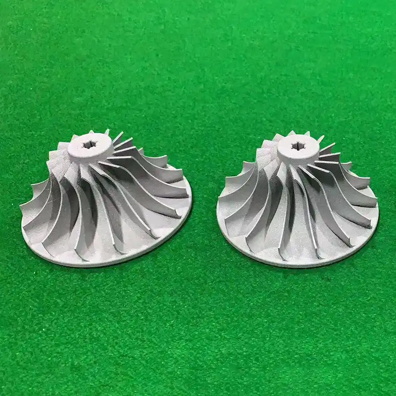
A 3D-printed sample can look like a finished component, but its material may be very different from the material used in production. The choice depends on what the sample needs to prove: appearance, fit, assembly, or performance.
what are 3d prints made of?

Before a 3D printer can produce a sample, it needs a digital model of the part. In manufacturing, this file carries the geometry that engineers want to turn into a physical component.
what are 3d printing files called?