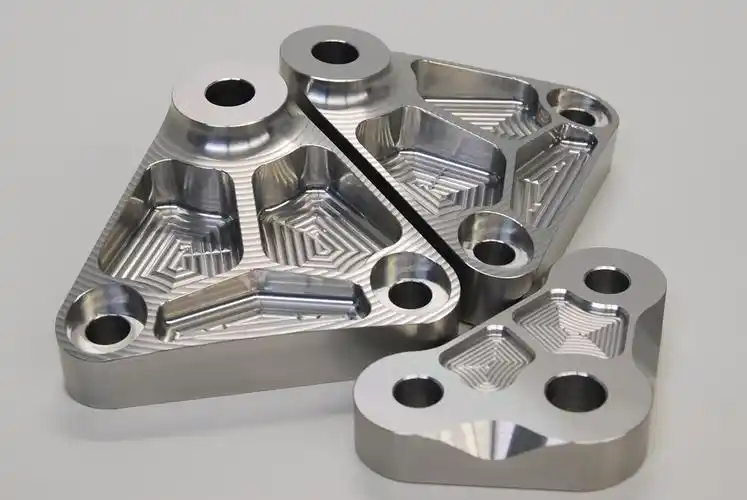
How to Create 3D Print Files: Complete Industrial Workflow for Hardware & Mold Sampling
Author: SZTC
2026-09-30
In hardware processing and plastic mold manufacturing, 3D rapid sampling relies entirely on high-quality printable digital files. Many workshop printing failures, dimensional deviations, surface defects and assembly errors are not caused by printer or material issues, but by unqualified 3D print files. Most engineers directly export CAD files designed for CNC machining or injection molding without professional conversion and optimization, resulting in unprintable models and delayed sampling progress. For industrial technicians engaged in rapid prototyping, the core operational skill is clear: how to create 3D print files that meet industrial standards for mold cavity verification and hardware functional testing. This article elaborates a standardized full-process workflow to generate error-free, high-precision 3D print files for factory rapid sampling scenarios.
1. Understand Standard 3D Print File Formats for Industrial Use
Before learning how to create 3D print files, it is essential to master mainstream industrial file formats and their applicable scenarios. Different formats carry different data attributes, directly determining printing precision and equipment compatibility.
1.1 STL: The Universal Industrial Printing Format
STL (Standard Tessellation Language) is the most widely adopted format for mold and hardware 3D printing. It converts complete 3D CAD models into triangular mesh surfaces, recording only geometric contour data without parameter or color information. With full compatibility with all FDM, SLA, SLS and metal printing equipment and slicing software, STL is the default standard for industrial rapid sampling. It is lightweight, stable and easy to repair, fully meeting the iteration and verification needs of daily mold samples and hardware fixtures.
1.2 3MF: High-Precision Modern Alternative
3MF is a new-generation 3D manufacturing format that makes up for STL’s technical defects. It supports complete data storage, including mesh details, color information and printing parameters, with smaller file size and no mesh distortion. For high-precision plastic mold samples with complex curved surfaces and fine textures, 3MF can retain more design details and avoid facet distortion caused by low-precision STL export. It is gradually becoming the preferred format for high-standard industrial prototyping.
1.3 OBJ and Other Auxiliary Formats
OBJ formats are mainly used for models with surface texture and color requirements, suitable for appearance simulation of plastic mold samples. However, they have poor compatibility with industrial metal printing equipment and are not suitable for hardware structural parts and high-strength mold inserts. In formal industrial sampling, STL and 3MF are still the core mainstream formats.
2. Pre-File Creation Industrial Design Standards
Qualified 3D print files must be based on printable industrial models. Standardized model design is the prerequisite to solve how to create 3D print files with zero defects.
2.1 Watertight and Manifold Model Requirements
The most fundamental standard for printable files is a completely watertight and manifold structure. All model surfaces must be closed with no open edges, tiny gaps, overlapping meshes or internal broken faces. Non-watertight files cannot generate effective slicing paths, causing printing interruption, hollow layers and structural collapse. For thin-wall mold cavities and intricate hardware assembly parts, mesh integrity inspection must be stricter to eliminate microscopic defects.
2.2 Process-Matched Structural Parameters
Optimize structural parameters according to printing processes before file export. Reserve 0.8mm minimum wall thickness for SLA mold samples and 1.2mm for FDM hardware parts. Follow the 45-degree self-support rule to reduce redundant support structures, and add rounded transitions to sharp corners to release printing stress. Unreasonable structural parameters will lead to qualified CAD models but unqualified print files.
2.3 Unit and Dimension Calibration
3D print files do not carry unit information, making unit error the most common industrial mistake. All mold and hardware models must be confirmed in millimeters before export. Compare overall dimensions with design drawings to avoid size deviation caused by inch and millimeter confusion, ensuring the printed sample matches industrial assembly standards.
3. Step-by-Step Guide: How to Create 3D Print Files
This standardized industrial workflow covers model optimization, file export, mesh repair and parameter calibration, fully answering how to create 3D print files for qualified rapid sampling.
3.1 Model Optimization for Additive Manufacturing
Convert traditional CNC and mold design models into additive manufacturing-friendly structures. Remove unprintable tiny blind holes, ultra-thin residual walls and unreasonable undercut structures. Optimize wall thickness uniformity to avoid abrupt thickness changes that cause thermal deformation. For plastic molds, retain draft angles and cavity texture details; for hardware parts, strengthen load-bearing structures and assembly tolerance positions to ensure the model meets printing feasibility and functional verification requirements.
3.2 High-Precision File Export from CAD Software
Use industrial CAD software such as SolidWorks, Fusion 360 and UG NX for standardized export. Select STL or 3MF format according to sampling precision requirements. Adjust export precision parameters appropriately: set high chord tolerance for fine mold texture samples to restore curved surface details, and adopt standard precision for ordinary hardware structural parts to balance file size and slicing speed. Avoid low-precision export that causes facet distortion and detail loss.
3.3 Professional Mesh Inspection and Defect Repair
Exported original files inevitably have tiny mesh errors. Import files into mesh repair tools to detect and fix open edges, flipped normals, overlapping faces and non-manifold vertices. Complete full watertight verification to ensure the file forms a closed and printable entity structure. This step is crucial for transforming flawed design files into industrial-grade 3D print files, eliminating most potential printing risks.
3.4 Printing Scenario Secondary Optimization
Optimize files according to specific printing processes and materials. For resin mold printing, smooth local rough meshes to improve surface simulation effect. For hardware engineering material printing, adjust internal structure rationality to enhance layer bonding strength. For metal printing mold inserts, optimize stress concentration areas in files to prevent thermal cracking during laser melting.
3.5 Final Preview and Standard File Saving
Preview the repaired file in slicing software to check for missing structures, abnormal meshes and unprintable areas. Confirm dimensional tolerance, structural integrity and printing feasibility again. Save and classify files according to project numbers and sample types to facilitate subsequent batch printing and version iteration management.
4. Scenario-Based File Creation Skills for Mold & Hardware
Different industrial sampling scenarios require targeted file creation strategies to maximize sample quality and efficiency.
4.1 Plastic Mold Sample File Creation
Focus on detail retention and surface smoothness when creating mold print files. Improve export precision to restore tiny cavity grooves, curved surfaces and texture features. Simplify non-functional redundant structures and retain complete demolding and cooling channel structures. Ensure the file can truly simulate injection molding effects and support mold flow analysis and structural optimization verification.
4.2 Hardware Functional Sample File Creation
Prioritize structural stability and assembly accuracy for hardware print files. Optimize hole position tolerance and thread structure clearance, reserve 0.1mm-0.2mm shrinkage compensation for assembly parts. Ensure uniform wall thickness and reasonable stress distribution in the file to make the printed sample pass mechanical strength testing and fixture assembly verification.
5. Common File Creation Mistakes and Solutions
Avoiding typical errors effectively improves the yield of industrial rapid sampling and reduces rework costs.
5.1 Direct Export Without Mesh Repair
Most original CAD exported files have hidden mesh defects. Direct slicing and printing without repair will cause layer dislocation, local hollowing and sample scrapping, wasting materials and sampling time.
5.2 Low-Precision Export Parameter Settings
Excessively low export precision leads to serious curved surface faceting, losing mold texture details and affecting hardware assembly accuracy. Always match high-precision parameters for industrial sample file creation.
5.3 Ignoring Unit and Tolerance Calibration
Neglecting unit confirmation and shrinkage compensation results in unqualified sample dimensions, making mold cavities unable to demold and hardware parts unable to assemble normally.
6. Conclusion
In summary, the complete solution to how to create 3D print files for hardware and plastic mold rapid sampling covers format selection, model DfAM optimization, high-precision export, mesh defect repair and scenario-based secondary calibration. Qualified industrial 3D print files are not simple converted CAD files, but optimized, repaired and verified printable files that adapt to additive manufacturing rules. Mastering standardized file creation workflows can effectively reduce printing failure rates, shorten product iteration cycles, and provide stable, high-precision digital file support for factory rapid sampling, helping manufacturing enterprises improve R&D efficiency and market response speed.


Samuel Song Your service representative
samuel@chnzhongzhu.com WhatsApp:+86 18688963321
Specializing in zinc-aluminum-magnesium alloy die-casting processing, CNC milling, CNC turning, 3D printing, injection molding and sheet metal processing. Manufacturing services.
How to Create STL Files: Industrial Step-by-Step Guide for Hardware & Mold Rapid Sampling
How to Create 3D Print Designs: Industrial DfAM Guide for Hardware & Mold Sampling
Related Article
This guide explains the relationship between AI, machine learning and deep learning in practical terms. It covers how the technologies differ, how they work, where they are used, and what they mean for industrial manufacturing, quality inspection and CNC machining.
Is Machine Learning Part of AI?
This guide is written for mechanical engineers, industrial equipment buyers, maintenance professionals and manufacturing procurement teams. It explains how oil reduces friction, how different lubrication mechanisms work, which oil properties matter, and where lubrication is used in industrial machinery.
How Does Oil Between Machine Parts Reduce Friction?