which parts of a machine must be guarded?
Which Parts of a Machine Must Be Guarded? A Practical Guide to Machine Guarding Compliance for Industrial Buyers
Most plant managers do not lose sleep over the theory of machine guarding. They lose sleep over the practical version: will this supplier identify every pinch point on my line, will the guard clear the door and maintenance access, will the interlock cut power when the panel opens, and will the installation pass the next safety audit before the production shift starts. That is the real reason people search which parts of a machine must be guarded at eleven at night with a machine layout drawing open on a second screen.
This guide is written for procurement engineers, maintenance leads and safety teams who need to specify or source machine guards rather than read a safety textbook. It covers the hazard points that require protection, the guard types and standards our shop works to, the materials and fabrication options available, the industries they serve, and a selection checklist you can reuse on every guard RFQ. Every compliance reference in the specification section is traceable, because a supplier that cannot document its guarding design should not be quoting your equipment.
- Which Parts of a Machine Must Be Guarded?
- Common Machine Components Requiring Guards
- Guarding Standards and Technical Parameters
- Industrial Applications of Machine Guards
- How to Select a Machine Guarding Supplier: 8 Steps
- FAQ: Machine Guarding Requirements and Capabilities
- Conclusion and Quote Request
Which Parts of a Machine Must Be Guarded?
Machine guarding means a physical barrier or protective device placed between an operator and a machine hazard: rotating parts, reciprocating motion, shearing edges, nip points, flying chips or sparks. The guard keeps hands, arms, clothing and hair out of the danger zone, while leaving the machine operable, serviceable and inspectable. A hazard assessment identifies the exposed motion; the guard design then contains it to a defined clearance.
The practical consequence is simple: the protection lives in the barrier, not in operator discipline. Repeat shifts two years later still face the same protected opening, and any gap appears as a dimension in a guard fit report rather than an argument. That repeatability is why custom machine guards became the default route for safeguarding production equipment, rather than relying on warning labels or "be careful" procedures.
A typical guard project runs through six stages: hazard review against the machine layout, guard concept and DFM feedback, panel fabrication with bracket and hinge design, fit-up with interlock or latch hardware, deburring and surface treatment, then final inspection, fit verification and packing. A competent supplier flags openings that cannot be reached safely or panels that block maintenance during quotation, not after the first install fails the audit.
What guarding is not matters just as much. It is not a cosmetic enclosure, so a cover that leaves the drive side exposed does not count as protection. It is not a fixed wall that locks out maintenance, because guards must allow safe access for setup, clearing jams and lubrication. It sits between an exposed machine and a fully enclosed cell: the right route for point-of-operation protection, drive covers, conveyor barriers and any station where motion hazard drives the specification more than panel price.
Our shop runs one-stop custom guard fabrication and machining, not catalogue covers. We do not stock universal guard panels and we do not resell. Every guard is produced from your layout or model, in the material and finish you specify, sized to the clearance you call out, and documented with the fit and inspection reports your safety team will ask for. If you need a standard stock safety fence, we will say so and point you elsewhere; if you need a shaped interlocked cover around a 5-axis spindle with a 0.005 mm clearance to the moving part, that is our job.
Common Machine Components Requiring Guards
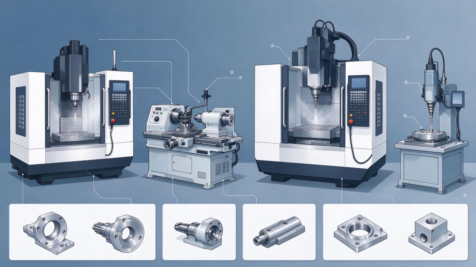 The requirement covers a family of hazard points. Missing one changes the audit outcome, so it helps to know what each component exposes.
Rotating shafts, spindles and couplings expose a winding hazard where clothing or hair can catch. Exposed shaft ends, keyways and universal joints are covered by fixed or telescopic guards that follow the shaft length without touching the rotating surface.
Gears, sprockets, chains, belts and pulleys create nip points where two surfaces meet. The drive train must be enclosed on both the tight and slack sides; open chain runs and V-belt drives are common audit findings because the guard was fitted only over the pulley.
Flywheels, drums and wheels present both rotation and crush risk near their contact surfaces. Guards here must contain the wheel or drum and keep the gap to the frame within the clearance allowed by the guarding standard.
Point-of-operation tools — saw blades, milling cutters, drill heads, press rams, shear blades and punch dies — are the highest-risk zone. They usually call for interlocked or adjustable guards that move with the workpiece rather than a static cover, because the operator must feed material into the cut safely.
Reciprocating slides, rams and rods expose a shearing or crushing path between the moving member and the frame. The guard covers the stroke envelope, and pinch points at the ends of travel are checked separately from the side panels.
Conveyors, feed rolls and rack-and-pinion drives create in-feed nips and moving rails. Roll nips are protected by self-adjusting guards or hold-downs, while conveyor side runs use mesh or sheet barriers along the exposed length. Robotic cells and welding stations add perimeter fencing with interlocked access gates rather than individual part guards.
Guarding Standards and Technical Parameters
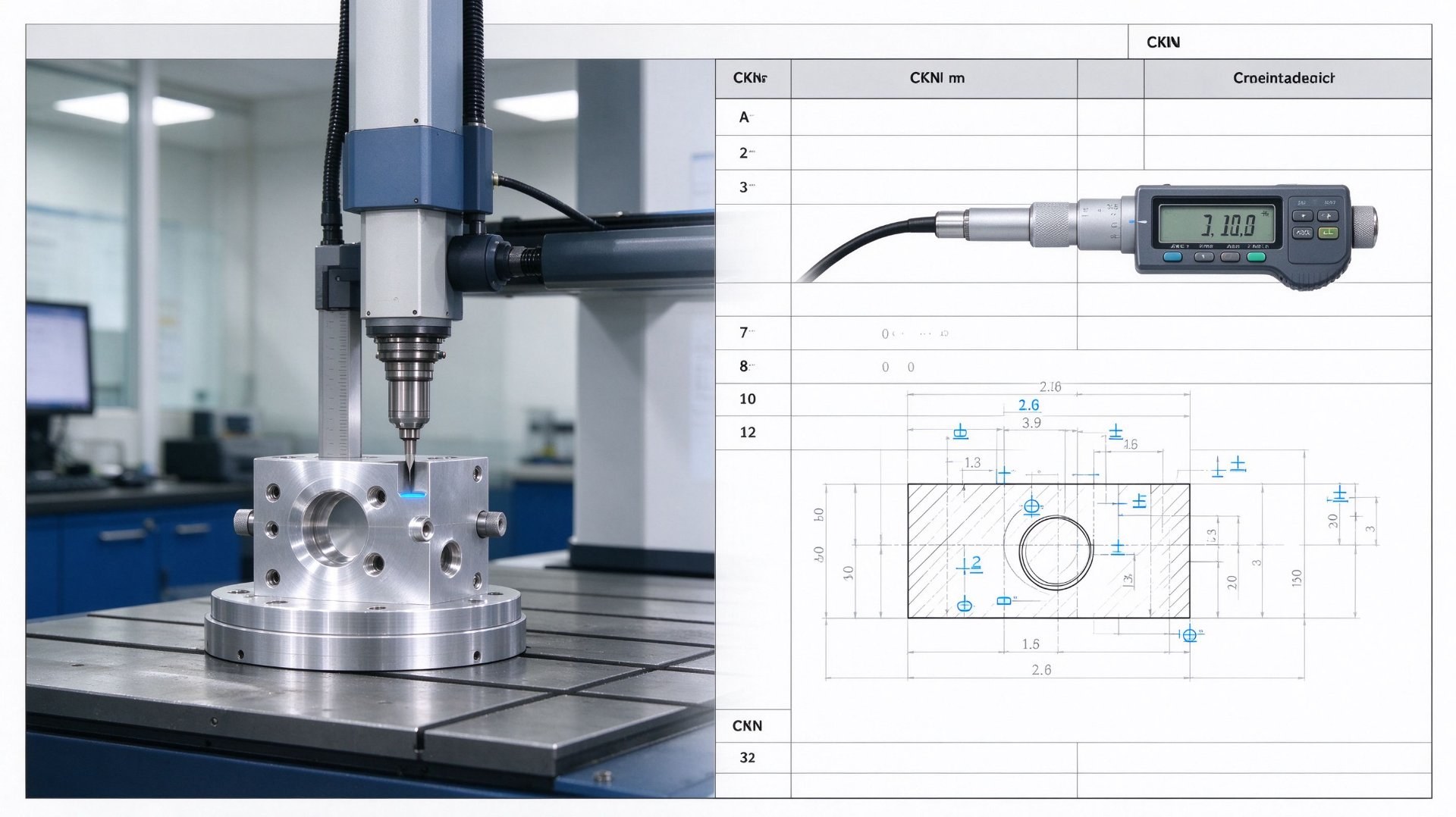 The table states the guard design bands our fabrication floor quotes against. Any opening, clearance or interlock arrangement outside these bands needs an engineering review before we commit, because promising a guard a standard does not accept is the fastest way to fail a safety audit.
| Parameter | Capability | Typical Use |
|---|---|---|
| Hazard type covered | Rotation, reciprocation, shear, nip, flying chips and sparks | Drive trains, point-of-operation tools, feed rolls |
| Guard type | Fixed, interlocked, adjustable, self-adjusting, perimeter fence | Permanent covers, access panels, in-feed protection, robot cells |
| Compliance standard | OSHA 29 CFR 1910.212 / 1910.219, ISO 14120, ISO 13849-1 | General machine guarding, power transmission, safety interlock performance |
| Guard material | Steel sheet, aluminum plate, polycarbonate, acrylic, welded wire mesh | Solid barriers, clear sight panels, ventilation and chip screens |
| Opening clearance | Gap and distance per OSHA 1910.212 Table O-14 for the hazard size | Mesh openings, panel slots, access-door gaps |
| Fastening and access | Fixed guards require tool removal; interlocked panels cut power on opening | Permanent covers, service doors, maintenance hatches |
| Panel fabrication | Bent/welded sheet metal, machined brackets, framed clear panels | Custom housings, mounting frames, hinge and latch assemblies |
| Order quantity | 1 prototype guard, no tooling charge | Single-machine retrofit, line-wide safety upgrade |
| Lead time | 5–7 working days for prototype guards, 12–18 working days for 10–100 panels | Audit preparation and production-line scheduling |
| Verification package | Fit report, clearance check, material certificate, inspection photographs | Supplier qualification and safety audit records |
Material coverage. Steel sheet for impact-resistant solid barriers and welded frames; aluminum plate for lightweight covers that must be removed often; polycarbonate and acrylic for clear panels where operators need to see the cutting zone; welded wire mesh for ventilation, airflow and chip screens; and rubber or brush strips for flexible in-feed closures. Visibility, impact resistance and whether the station needs ventilation decide the material, not default preference.
Surface treatment and inspection. Powder coating, anodizing, sandblasting and zinc plating, each specified with a standard and colour reference, because "grey painted cover" alone is not a purchasing specification. Inspection checks panel dimensions, opening gaps, hinge and latch alignment, interlock fit-up and mounting hole positions against the machine layout.
Data sources: design bands come from our internal fabrication capability list and inspection standard, November 2026; general guarding requirements follow OSHA 29 CFR 1910.212 and 1910.219; machinery safety principles follow ISO 14120:2015; interlock performance follows ISO 13849-1.
Industrial Applications of Machine Guards
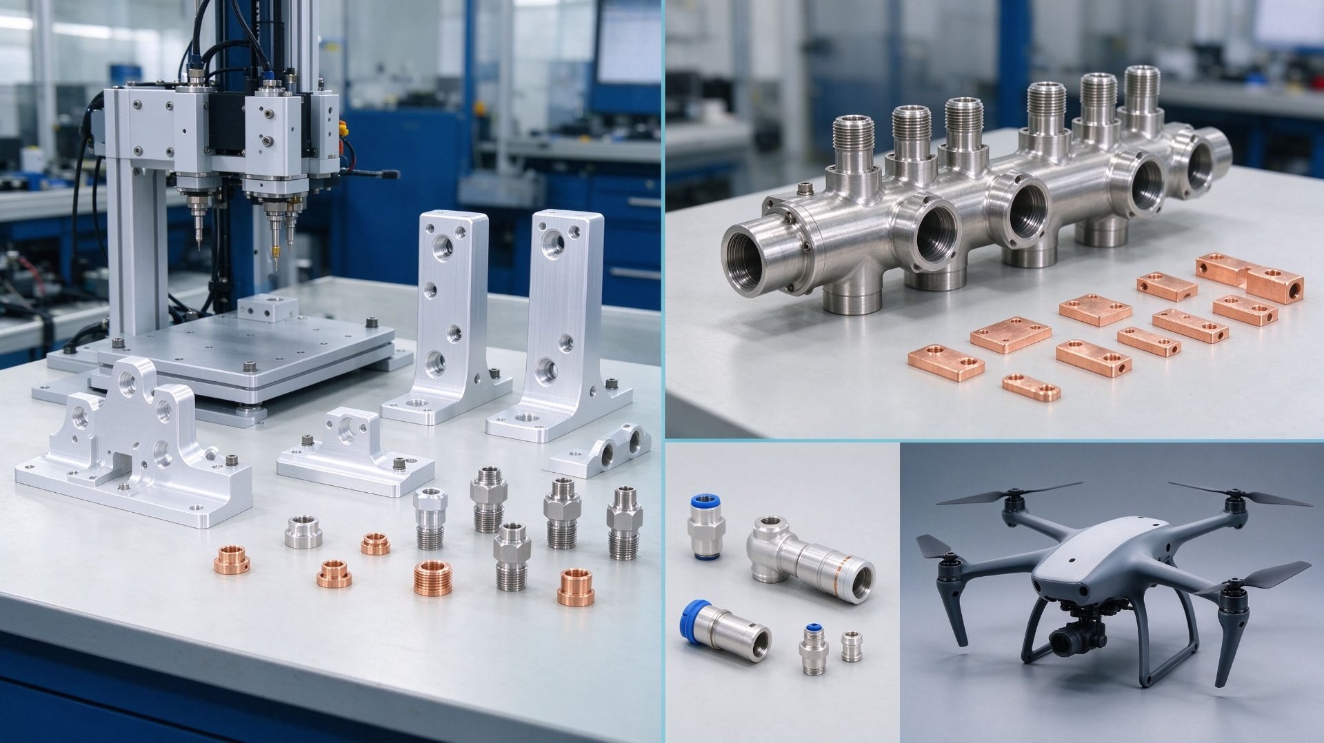
Custom guards appear across these production sectors, and each one stresses a different guarding capability.
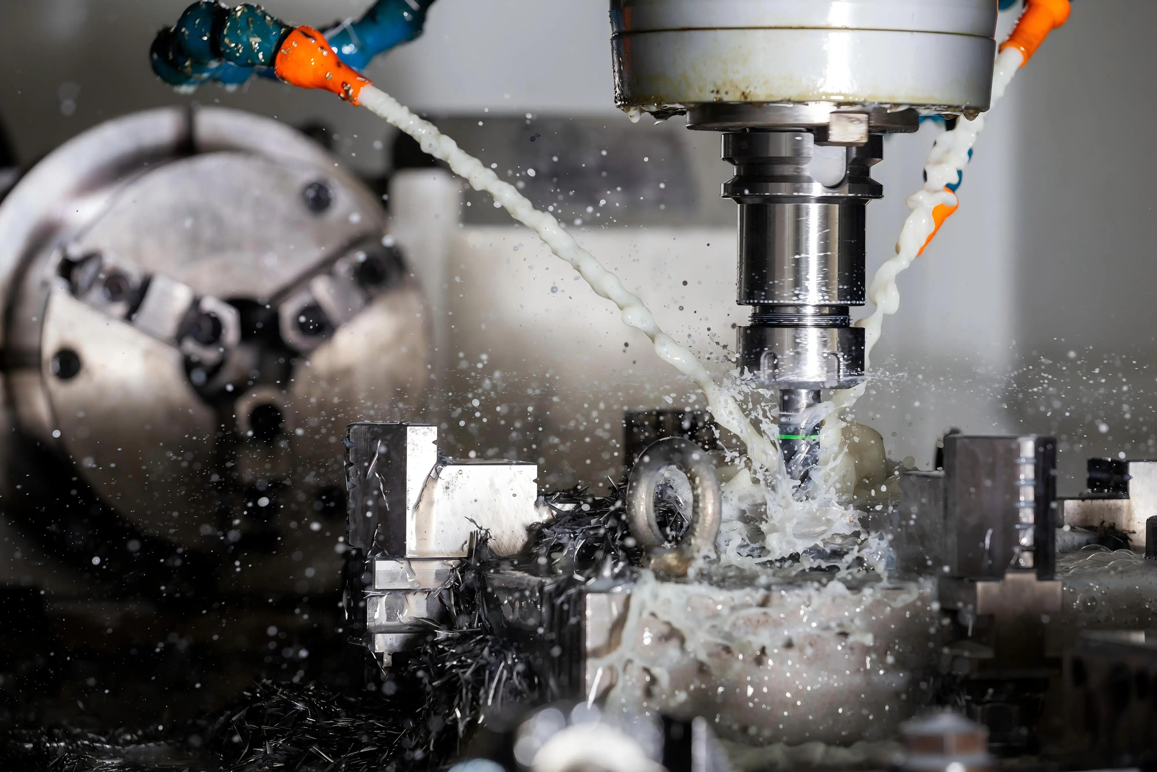
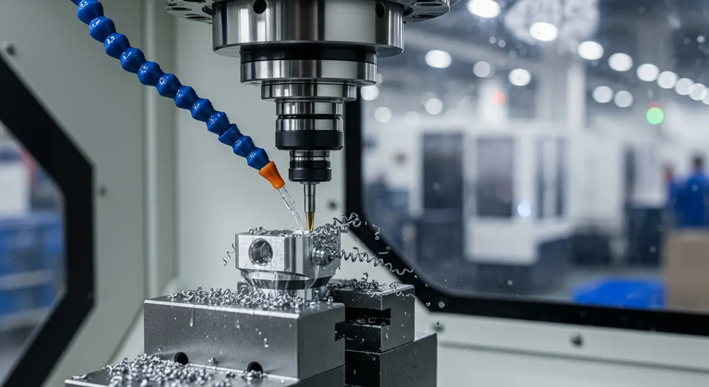
CNC machining and turning centres. Spindle covers, chip shields, door panels and enclosures around mills, lathes and machining cells. Clear sight panels protect the operator from flying chips while keeping tool change and setup access usable.
Press brakes, shears and stamping presses. Point-of-operation barriers, light-curtain-compatible frames and adjustable die-area guards. Ram stroke envelopes and end-of-travel pinch points are the recurring hazard, and guard rigidity under repeated press cycling matters as much as coverage.
Conveyors and packaging lines. Side barriers, feed-roll nips, transfer-point guards and drive-chain enclosures. Long line runs call for modular panels that repeat along the exposed length, with access gates at maintenance crossings.
Robotics and automation cells. Perimeter fencing, interlocked access gates, mesh walls and safety-scanner-compatible layouts. Cell boundary height, gate interlock and free space behind the guard are specified together rather than panel by panel.
Woodworking, sawing and grinding stations. Blade guards, dust collection hoods, abrasive-wheel shields and adjustable anti-kickback protection. Dust extraction, spark clearance and visibility into the cut zone drive the panel design.
Assembly lines and pneumatic equipment. Rod covers, slide guards, fixture shields and force-fit station barriers. This is the volume backbone of most guarding retrofits, and it rewards stable fabrication consistency more than exotic custom geometry.
How to Select a Machine Guarding Supplier: 8 Steps
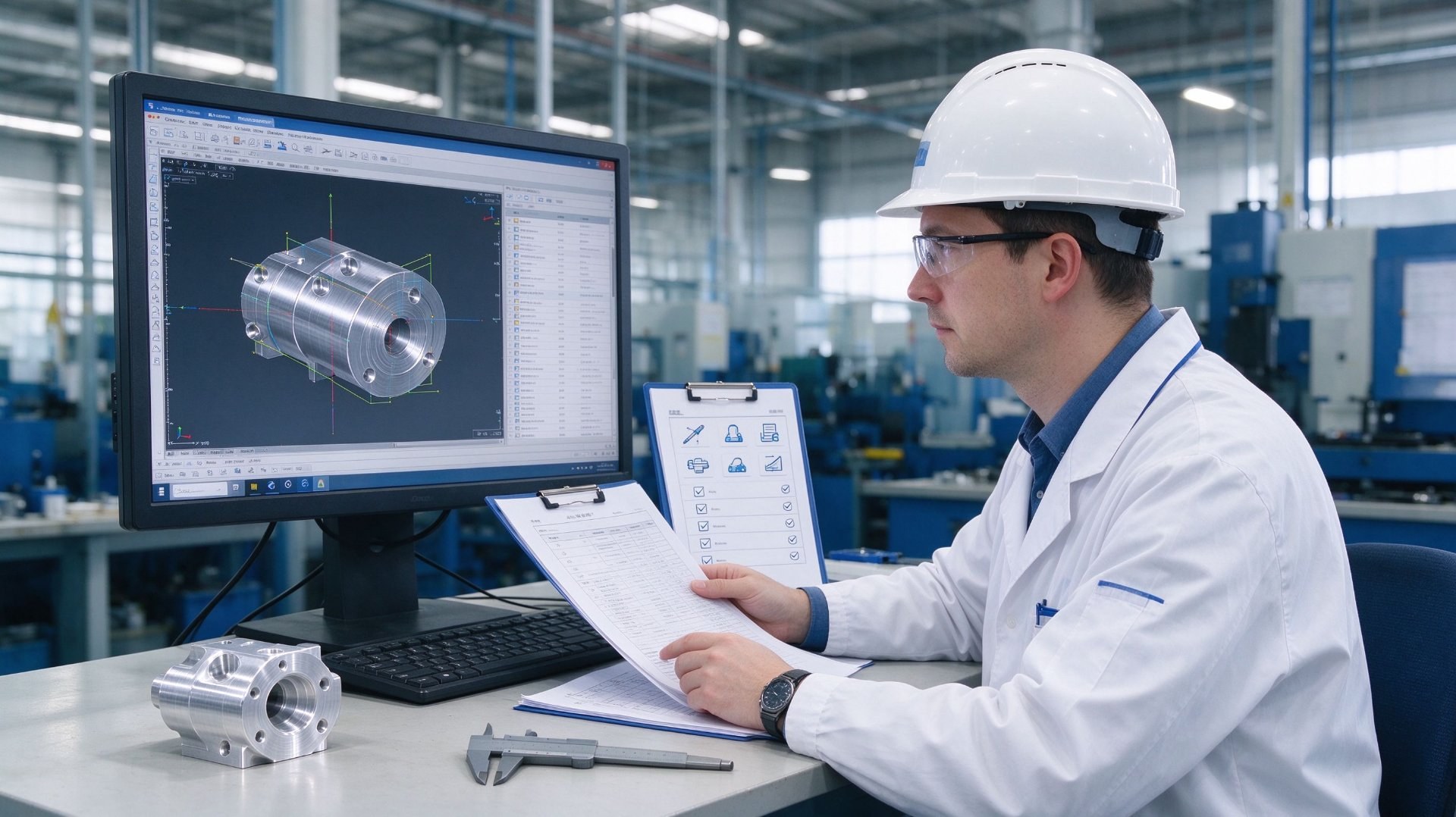
Most guarding failures are predictable and can be avoided before the purchase order is issued. This sequence is the one we recommend to buyers evaluating us and to buyers evaluating anyone else.
Step 1: Send a complete data package. Machine layout or 3D model, hazard description, motion directions, access points and the standard you audit against. A model alone leaves clearance and access requirements to interpretation, and interpretation is where audit findings start. State quantity, target date, destination country and installation requirement.
Step 2: Ask for guarding DFM feedback before price. A serious supplier comments on panel reach, hinge and latch placement, tool access, sightline gaps and whether your interlock arrangement fits the geometry. A quote with no technical questions usually means the hazard was not reviewed.
Step 3: Verify compliance with evidence. Ask which standard applies to which hazard, how opening gaps are measured, and whether the clearance figure comes from a standard table or a best-case guess. Request a fit report from a comparable guarded machine.
Step 4: Confirm material and traceability. Ask for the material certificate, sheet or plate grade, and whether substitution is permitted between steel, aluminum and clear panel stock. For impact-resistant and welded-frame guards this is non-negotiable.
Step 5: Order a prototype guard and fit-check it yourself. Test the features that matter, not the easy ones: panel clearance, door opening, interlock function, latch alignment and visibility to the hazard. A prototype that fits on your machine removes most of the risk from the line-wide order.
Step 6: Agree the inspection package up front. Fit report, clearance check, material certificate, treatment certificate and installation photographs. Define full inspection for critical openings before production, not after an audit rejection.
Step 7: Lock schedule, logistics and risk sharing. Confirm lead time from layout approval rather than inquiry, agree what happens if hardware or material is delayed, and choose terms matching your risk: courier for prototype panels, air freight for urgent retrofit, sea freight for planned volume.
Step 8: Compare total cost, not panel price. A cheaper cover with poor fit, missing clearance data and non-repeatable fabrication costs more in rework, lost production time and repeat audit findings.
FAQ: Machine Guarding Requirements and Capabilities
Each answer matches the specification table above. Where a standard or figure is quoted, the source is stated so your safety team can verify it independently.
Q1: Which parts of a machine must be guarded?
A1: Any part that exposes an operator to rotation, reciprocating motion, shearing, crushing, nip points or flying debris must be guarded. This includes rotating shafts, spindles and couplings; gears, sprockets, chains, belts and pulleys; flywheels and drums; point-of-operation tools such as blades, cutters and press rams; reciprocating slides and rods; and conveyor in-feed rolls and moving rails. Warning labels alone are not a substitute for a physical barrier.
Source: OSHA 29 CFR 1910.212; ISO 14120:2015.
Q2: What types of guards are available?
A2: Fixed guards bolted or welded in place for permanent protection; interlocked guards that stop the machine when the panel opens; adjustable guards that move with the workpiece; self-adjusting guards for in-feed rolls; and perimeter fencing with interlocked gates for robot and automation cells. The type follows the hazard and the access the operator or maintenance requires.
Source: OSHA 29 CFR 1910.212; ISO 14120:2015.
Q3: What standards apply to machine guarding?
A3: In the US, OSHA 29 CFR 1910.212 covers general machine guarding and point-of-operation, while 1910.219 covers mechanical power transmission equipment. Internationally, ISO 14120 sets general guarding design principles, and ISO 13849-1 defines performance levels for safety-related interlock and control systems. Your audit standard should be stated on the drawing before fabrication starts.
Source: OSHA 1910.212, 1910.219; ISO 14120:2015; ISO 13849-1.
Q4: What materials are used for machine guards?
A4: Steel sheet and welded frames for impact-resistant solid barriers; aluminum plate for lightweight frequently removed covers; polycarbonate and acrylic for clear sight panels; welded wire mesh for ventilation and chip screens; and brush or rubber strips for flexible in-feed closures. Finish options include powder coating, anodizing, sandblasting and zinc plating.
Source: approved guard material list, factory fabrication manual.
Q5: When is an interlocked guard required instead of a fixed one?
A5: An interlocked guard is required wherever access to the protected zone is needed during normal operation, setup, jam clearing or adjustment, and where opening the guard would leave a hazard exposed. Fixed guards are acceptable only where the part is permanently enclosed and tool-removal access does not expose the motion.
Source: ISO 14120:2015; ISO 13849-1.
Q6: What opening gaps are allowed between a guard and a moving part?
A6: Mesh openings, slots and panel gaps must follow the opening-size to distance rules in OSHA 1910.212 Table O-14: larger openings require greater distance from the hazard, while smaller openings may sit closer. The allowed gap depends on the hazard size behind it, so clearance must be measured after the guard is fitted, not estimated from the panel drawing.
Source: OSHA 29 CFR 1910.212, Table O-14.
Q7: Can guards be custom fabricated for existing machines?
A7: Yes. Custom bent or welded sheet panels, machined mounting brackets, framed clear panels and hinge or latch assemblies can be made from your machine layout, 3D model or field measurements. One prototype guard is accepted with no tooling charge, so fit can be verified on the machine before a line-wide order is released.
Source: factory quotation policy; fabrication capability list, November 2026.
Q8: How is guard compliance verified before shipment and installation?
A8: With a fit report against the machine layout, clearance and opening-gap checks, material certificate, surface treatment record and inspection photographs of panel dimensions, hinges, latches and interlock fit-up. Critical openings are verified individually rather than accepted as a blanket panel check.
Source: ISO 9001:2015 aligned fabrication inspection procedure; guard verification checklist.
Conclusion and Quote Request
You now have a working answer to which parts of a machine must be guarded from a buying perspective: which hazard points require protection, which guard type fits each access pattern, which standards and clearances are realistic, how guarding maps onto industrial applications, and how to qualify a supplier before you commit a purchase order.
If your project needs custom fabricated machine guards in sheet metal, aluminum or clear panel stock, send your machine layout and 3D model with hazard description, material, finish and target date. Our engineering team will review the guarding concept, confirm the clearance and standard that apply to each critical opening, and return a quotation with lead time and inspection plan. No catalogue covers, no reselling, no vague promises: we build what you specify and document what we ship.
Get In Touch
Ready to source custom machine guards and fabricated panels for your equipment? Contact us today.
📄 Request a Technical Datasheet
Contact Us →📞 Speak with Our Engineering Team
Get In Touch →🔗 Browse Our Custom Fabrication Solutions
View Products →Dongguan A&S Power Technology Co., Limited.
315 PING 'AN AVENUE, PINGHU STREET, LONGGANG DISTRICT,
SHENZHEN CITY, GUANGDONG PROVINCE
📞 +86 18688963321
✉ samuel@chnzhongzhu.com
Precision Parts. Proven Process.


Does porsche ag manufacture cars requiring cnc machined parts?
Related Article