
How to 3D Print Metal: Industrial Guide for Hardware and Mold Rapid Sampling
Author: SZTC
2026-09-24

In the plastic mold and hardware processing industries, traditional metal prototype production relies on CNC milling, turning, and manual machining. These subtractive methods involve high material waste, long lead times, and high costs for complex structures such as conformal cooling channels, special-shaped fixtures, and thin-wall mold inserts. Today, metal 3D printing has become a mainstream rapid sampling solution, enabling factories to produce high-strength, high-precision metal parts within days. For manufacturing engineers and workshop technicians engaged in rapid prototyping, the most valuable technical question is clear: how to 3D print metal to meet industrial mold and hardware testing standards. This article provides a complete, factory-oriented operational guide, covering process selection, design rules, standardized workflows, and post-processing skills for industrial metal 3D printing.
1. Overview of Industrial Metal 3D Printing Technologies
Before learning specific operations, beginners must master mainstream metal printing processes used in mold and hardware rapid sampling. Different technologies vary in precision, strength, cost and application scenarios, which is the primary premise to answer how to 3D print metal correctly.
1.1 SLM / DMLS Laser Melting Technology
Selective Laser Melting (SLM) and Direct Metal Laser Sintering (DMLS) are the most widely used industrial metal printing technologies for high-precision sampling. By spreading thin layers of metal powder and melting each layer with a high-power fiber laser in an inert gas environment, the processes produce fully dense metal parts with mechanical properties close to forged metal. These technologies are suitable for printing mold steel inserts, stainless steel hardware fixtures, and aluminum alloy structural prototypes that require high strength and tight tolerance. With XY precision up to ±15μm and ultra-thin layer thickness, they fully meet industrial assembly and strength testing requirements.
1.2 Metal Binder Jetting Technology
Metal binder jetting is a cost-effective solution for medium-precision and batch metal sampling. It uses a bonding agent to shape metal powder layer by layer, followed by high-temperature sintering to improve density and hardness. Compared with laser melting equipment, binder jetting machines have lower operating costs and higher production efficiency. They are commonly used for low-tolerance hardware structural parts and ordinary mold auxiliary components, ideal for cost-controlled rapid verification projects.
1.3 Metal FDM Sintering Technology
2. Industrial Design Rules for Metal 3D Printing
Different from plastic 3D printing and traditional CNC machining, metal additive manufacturing has strict structural design constraints. Standardized design optimization is the core step of how to 3D print metal to avoid deformation, cracking and printing failure.
2.1 Minimum Wall Thickness Standards
Metal printing cannot support ultra-thin wall structures due to laser melting stress and powder melting characteristics. For SLM high-precision mold and hardware parts, the safe minimum wall thickness is 1.0mm to 1.2mm. For binder jetting parts, the wall thickness should not be less than 1.5mm to prevent layer fracture and structural hollowing. Abrupt thickness transitions must be avoided; uniform wall thickness distribution helps balance thermal stress and greatly reduce warping and cracking risks during printing and cooling.
2.2 Support Structure Optimization Rules
Metal printing generates huge thermal stress during laser melting, making support structures indispensable for overhanging and suspended features. Unlike plastic printing supports, metal supports not only fix the model position but also conduct heat and release stress. All structures with an inclination angle below 45 degrees need reasonable support layout. For key mold cavity surfaces and hardware assembly planes, designers should optimize support distribution to avoid dense support marks, reserving enough space for subsequent polishing and finishing.
2.3 Hole and Cavity Structure Design
Small deep holes and fully enclosed cavities are prone to powder accumulation, resulting in difficult cleaning and internal defects. For mold cooling holes and hardware positioning holes below 2mm, properly expand the aperture or add process holes for powder discharge. For conformal cooling channels inside mold inserts, optimize the pipe curvature to ensure smooth powder removal and complete melting, ensuring the printed channel meets actual injection molding cooling efficiency standards.
3. Standard Step-by-Step Workflow: How to 3D Print Metal
Combined with actual mold and hardware rapid sampling scenarios, the standardized full-process operation completely solves how to 3D print metal for industrial qualified parts.
3.1 Pre-Print Model Repair and Optimization
Most original CNC models have non-printable defects such as non-watertight meshes, tiny gaps and unreasonable thin walls. The first step is to repair mesh errors, unify wall thickness, and remove invalid overlapping structures. According to metal printing stress characteristics, add rounded corner transitions to sharp right-angle positions to reduce stress concentration. Complete DFM optimization targeted at metal additive manufacturing to ensure the model meets printing process requirements.
3.2 Material Selection and Equipment Inspection
Select matching metal powder materials according to sample usage: 316L stainless steel for corrosion-resistant hardware parts, AlSi10Mg aluminum alloy for lightweight structural prototypes, and mold steel powder for high-hardness mold inserts. Before printing, inspect equipment operating status, clean the recoater blade and printing screen, and check powder dryness and fluidity. Replace agglomerated powder to avoid uneven layer spreading and printing defects. Seal the printing chamber and fill inert argon gas to prevent metal oxidation during melting.
3.3 Slicing Parameter Setting and Printing
Import the optimized model into professional metal slicing software, set layer height, laser power and scanning speed according to precision requirements. For high-precision mold samples, adopt thin-layer scanning and high-density laser parameters; for ordinary hardware structural parts, appropriately improve printing speed to control costs. Arrange model orientation reasonably, place key functional surfaces upward, and generate standardized support structures. After parameter confirmation, start automatic printing, and monitor the first ten layers closely to ensure uniform powder spreading and stable laser melting.
3.4 Post-Print Cooling and Stress Relief
Metal parts have severe internal thermal stress after laser melting. Do not disassemble the parts immediately after printing. Keep the parts in the sealed chamber for natural cooling to room temperature to avoid rapid cooling deformation. For high-precision mold inserts and thick hardware parts, perform professional heat treatment to eliminate residual internal stress, improving part stability and mechanical durability.
4. Industrial Post-Processing for Mold and Hardware Samples
Raw printed metal parts have rough surfaces, residual supports and dimensional tolerance deviations. Standardized post-processing is essential to turn printed blanks into usable industrial samples.
4.1 Support Removal and Blank Trimming
Use professional cutting tools to remove metal supports, and trim residual support bumps and edge burrs. For precision mold cavity surfaces, adopt fine grinding to avoid surface damage. Clean residual metal powder in deep holes and cavities completely to prevent powder residue from affecting assembly and testing results.
4.2 Surface Polishing and Precision Calibration
According to sample requirements, perform sandblasting, fine polishing and mirror finishing. Mold inserts need high surface smoothness to simulate injection molding effects, while hardware fixtures only need flatness and deburring treatment. Use precision calipers and coordinate measuring instruments to calibrate key dimensions, compensate tiny tolerance deviations, and ensure the parts meet industrial assembly standards.
4.3 Performance Testing and Quality Inspection
Complete hardness testing, density inspection and structural stability verification for printed metal samples. Check for internal pores, cracking and melting defects. Qualified metal prototypes can be directly used for hardware strength testing, mold trial production and structural verification, completely replacing traditional machined samples.
5. Common Mistakes in Industrial Metal 3D Printing
Avoiding typical errors can effectively improve sampling yield and reduce rework costs in mold and hardware projects.
5.1 Directly Using Unoptimized CNC Models
Models designed for subtractive machining ignore metal printing stress and structural rules, which easily cause large-area cracking and deformation during printing. Professional additive design optimization must be completed before printing.
5.2 Unreasonable Support Layout
Too few supports cannot resist thermal stress and cause structural collapse, while excessive supports increase post-processing difficulty and damage precision surfaces. Balanced support layout is critical for metal printing success.
5.3 Ignoring Inert Gas Protection
Insufficient inert gas concentration leads to metal oxidation, resulting in rough surface, reduced hardness and unqualified mechanical performance, failing industrial testing standards.
6. Conclusion
In conclusion, the systematic answer tohow to 3D print metal for mold and hardware rapid sampling covers process selection, DFM design optimization, standardized printing operation and professional post-processing. Different from plastic printing, metal additive manufacturing focuses on stress control, structural stability and industrial mechanical performance. Mastering complete metal printing workflows enables processing factories to quickly produce complex mold inserts, custom hardware fixtures and functional metal prototypes, greatly shortening R&D cycles, reducing CNC machining costs, and improving market competitiveness in rapid customized sampling services.


Samuel Song Your service representative
samuel@chnzhongzhu.com WhatsApp:+86 18688963321
Specializing in zinc-aluminum-magnesium alloy die-casting processing, CNC milling, CNC turning, 3D printing, injection molding and sheet metal processing. Manufacturing services.
How to 3D Print STL File: Full Industrial Workflow for Mold and Hardware Sampling
How to 3D Print for Beginners | Step-by-Step Guide for Mold & Hardware Sampling
Related Article

Machine parts are essential crafting materials in Fortnite: Save the World. They are used to craft weapons and traps, so running short can slow down mission progress.
what is the meaning of machining?
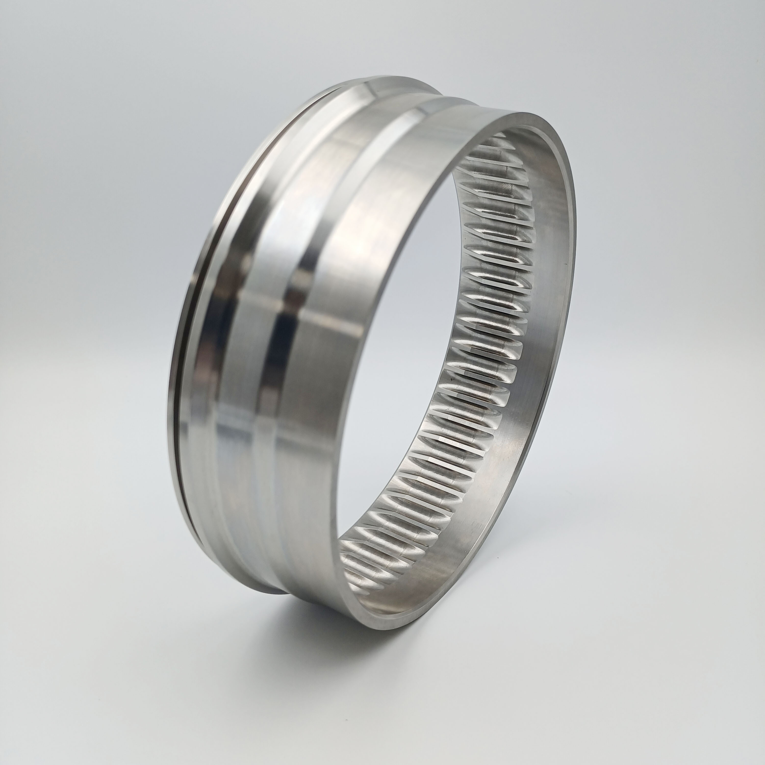
In hardware machining and plastic mold manufacturing, machines use rotating, cutting, pressing, and moving components to shape materials. These parts can create serious hazards if workers come into contact with them during operation.
what is machining?
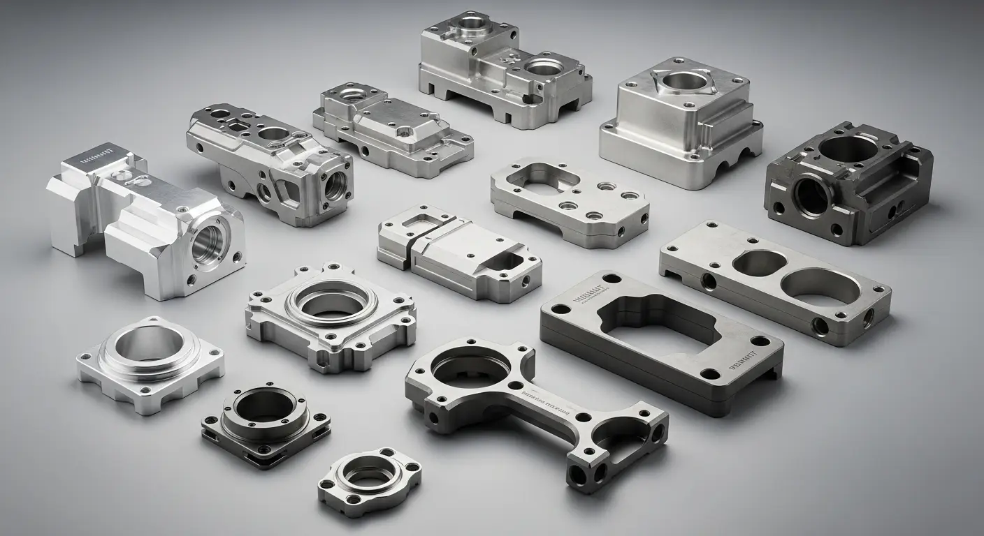
Machine parts are essential crafting materials in Fortnite: Save the World. They are used to craft weapons and traps, so running short can slow down mission progress.
how to collect machine parts in save the world?
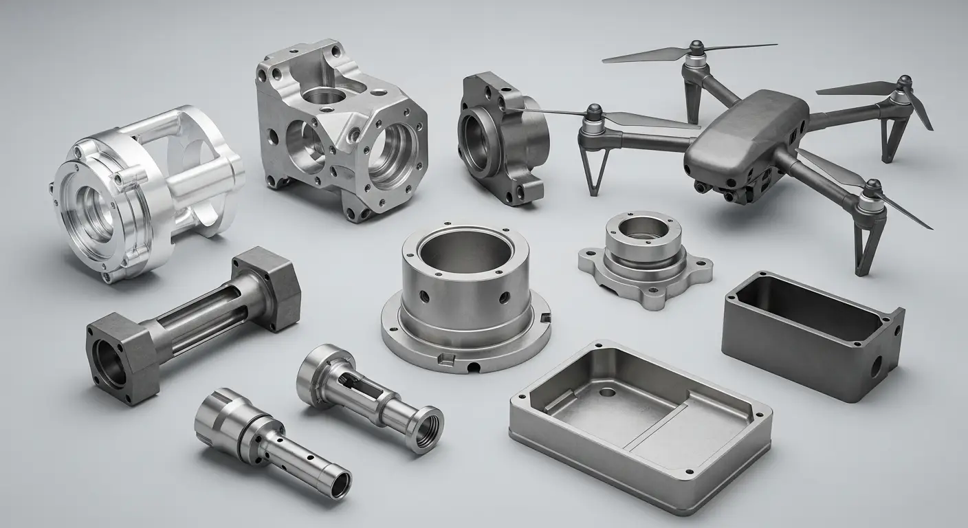
In hardware machining and plastic mold manufacturing, machines use rotating, cutting, pressing, and moving components to shape materials. These parts can create serious hazards if workers come into contact with them during operation.
which of the following machine parts always require guards?