
How to Create 3D Models for Printing: Industrial Guide for Hardware & Mold Sampling
Author: SZTC
2026-09-29
3D printing has become the backbone of rapid sampling in the hardware processing and plastic mold industries. It allows manufacturers to verify fixture structures, mold cavity designs, and custom mechanical parts within hours instead of days. However, most printing failures, dimensional errors, and weak functional prototypes stem from improperly designed 3D models that are built for CNC machining or injection molding rather than additive manufacturing. For industrial designers and workshop engineers focused on fast, reliable prototyping, one question remains central: how to create 3D models for printing that meet strict mold and hardware industrial standards. This article delivers a structured, factory-oriented workflow to build fully printable, high-performance 3D models for daily rapid sampling projects.
1. Understand Industrial Printing Design Logic
Before learning specific modeling steps, it is critical to rebuild design thinking. Traditional subtractive manufacturing and additive 3D printing follow completely different structural rules, which defines the core principle of how to create 3D models for printing.
1.1 Key Differences Between CAD Machining and 3D Printing Modeling
Models designed for CNC milling or injection molding allow ultra-thin residual walls, deep blind holes, sharp undercuts, and non-uniform structures. These features are unproblematic for cutting tools but cause severe printing defects such as layer collapse, warping, hollow gaps, and cracking during additive manufacturing. 3D printing builds parts layer by layer, so every structural detail must follow layer stacking mechanics, thermal shrinkage rules, and support logic. Industrial printable models prioritize manufacturability, structural stability, and post-processing feasibility while retaining core functional features for mold testing and hardware assembly.
1.2 Core Standards for Printable Industrial Models
A qualified industrial 3D model for mold and hardware sampling must meet three basic standards. First, the model must be watertight and manifold with no open edges, mesh gaps, or overlapping faces. Second, all wall thicknesses, hole tolerances, and overhang angles must match the selected printing process. Third, the structure must reserve space for post-processing, support removal, and assembly testing. These baseline requirements ensure the final printed sample can be used for formal structural verification and customer confirmation.
2. Pre-Modeling Preparation for Industrial Sampling
Standard pre-work lays the foundation for efficient and error-free modeling. Clarifying project requirements is the first step to master how to create 3D models for printing for targeted industrial scenarios.
2.1 Confirm Sample Application Scenarios
Different usage purposes determine modeling parameter settings. For plastic mold cavity samples, modeling focuses on surface texture restoration, draft angle design, and demolding structure optimization to simulate real injection molding effects. For hardware functional fixtures and load-bearing parts, modeling prioritizes wall thickness uniformity, stress dispersion, and assembly tolerance accuracy. Confirming the scenario in advance avoids over-designing non-key structures or missing critical functional details.
2.2 Select Matching Printing Process and Materials
Modeling parameters must adapt to printing technology. SLA resin printing for mold samples allows finer thin-wall structures and complex curved surfaces, while FDM hardware printing requires thicker and more uniform walls to enhance layer bonding. Metal 3D printing demands rounded corner transitions and reinforced structures to resist thermal stress and cracking. Material characteristics such as shrinkage rate, hardness, and toughness also need to be considered during modeling to reserve compensation tolerance.
2.3 Choose Professional Industrial Modeling Software
Industrial rapid sampling requires precise parametric modeling tools. Software including SolidWorks, Fusion 360, and UG NX are the most suitable choices for mold and hardware design. These tools support accurate dimension constraint, structural simulation, and mesh export, ensuring model consistency and editability. Avoid simple sculpting tools for industrial parts, as they cannot provide precise tolerance control required for assembly and strength testing.
3. Step-by-Step Workflow: How to Create 3D Models for Printing
This standardized industrial workflow covers full-process modeling from outline construction to final export, perfectly solving how to create 3D models for printing for qualified mold and hardware samples.
3.1 Build Constrained Basic Structural Outline
Start with accurate 2D sketching and full dimension constraint to avoid structural deformation during modification. Draw core profiles according to design drawings, and generate basic 3D shapes through extrusion, stretching, and hollowing operations. For mold plates and regular hardware jigs, maintain symmetrical and uniform structural distribution to balance printing stress. For special-shaped parts, prioritize the integrity of assembly datum surfaces and key positioning holes to ensure subsequent matching accuracy.
3.2 Set Standardized Industrial Wall Thickness
Wall thickness is the most critical parameter affecting printing yield and structural strength. For SLA mold samples, the minimum safe wall thickness is 0.8mm to ensure complete texture restoration. For FDM hardware parts, the wall thickness should be above 1.2mm to prevent layer fracture and deformation. For metal printing mold inserts, walls thicker than 1.0mm are required to form dense internal structures. Avoid abrupt thickness changes; use gradual transition structures to reduce warping and thermal shrinkage deformation.
3.3 Optimize Overhangs and Self-Supporting Structures
Follow the 45-degree self-supporting rule for industrial modeling. Structures with an inclination above 45 degrees can be printed stably without auxiliary supports. Optimize and adjust sharp overhanging structures below 45 degrees by adding chamfers, rounding corners, or lifting structural angles. Minimize redundant supports on key mold texture surfaces and hardware assembly planes to reduce post-polishing workload and avoid support mark defects.
3.4 Calibrate Holes, Tolerances and Shrinkage Compensation
3D printed parts have natural shrinkage during curing and cooling, leading to smaller actual dimensions than model data. During modeling, reserve 0.1mm to 0.2mm tolerance compensation for assembly holes and positioning grooves to ensure precise matching. For high-precision mold cavity gaps and thread structures, adjust the shrinkage value according to different materials to meet industrial assembly standards. Remove tiny blind holes and enclosed gaps that are easy to accumulate powder or resin and difficult to clean after printing.
3.5 Add Industrial Functional Optimization Details
For plastic mold samples, add standard draft angles on vertical walls to simulate real demolding performance and avoid undercut structures that affect mold trial verification. For hardware load-bearing parts, replace sharp right angles with rounded transitions to disperse stress concentration and improve structural toughness. For long-strip and large-area flat parts, add reinforcing ribs appropriately to prevent bending deformation during printing and use.
4. Model Inspection, Repair and Standard Export
Perfect modeling must be matched with strict final inspection to eliminate potential printing risks, which is an essential step for industrial rapid sampling.
4.1 Mesh Defect Detection and Repair
Import the completed model into mesh detection tools to check for open edges, non-watertight gaps, flipped normals, and overlapping faces. Most models converted from CNC drawings contain tiny mesh errors that must be repaired manually. Ensure the overall model forms a completely closed manifold structure to guarantee normal slicing and continuous printing path generation.
4.2 Printability Simulation Verification
Simulate layer stacking effects and structural stress distribution to check for easily deformed and collapsible positions. Optimize unreasonable local structures in advance to improve printing stability. Verify the rationality of support distribution, powder discharge space, and post-processing operability to ensure the model meets the full-process industrial printing standards.
4.3 Standard File Export
Export the final printable model in standard STL or 3MF format. Adjust mesh precision to balance printing accuracy and slicing speed, avoiding excessive mesh density that causes slow processing or low precision that loses industrial details. Classify and archive files according to project specifications to facilitate repeated sampling and version iteration.
5. Common Modeling Errors in Industrial Printing
Avoiding these frequent mistakes can effectively improve sampling qualification rate and reduce rework costs for mold and hardware projects.
5.1 Directly Using Unoptimized CNC Models
Models designed for cutting processing ignore additive manufacturing rules, containing unprintable thin walls, undercuts, and stress-concentrated structures. Direct printing without optimization will lead to mass sample scrapping.
5.2 Unreasonable Support-Dependent Design
Excessive reliance on manual supports without structural optimization will leave a large number of surface marks, affecting mold surface simulation and hardware assembly precision, and greatly increasing post-processing time.
5.3 Ignoring Material Shrinkage Differences
Universal modeling without targeted shrinkage compensation for different resins, engineering plastics, and metal powders will result in dimensional deviation and unqualified assembly effects.
6. Conclusion
In summary, the core answer tohow to create 3D models for printing in mold and hardware rapid sampling is to transform traditional machining thinking into additive manufacturing design logic. Qualified industrial 3D models require scenario-based structural optimization, standardized wall thickness and tolerance setting, reasonable overhang and stress design, as well as strict mesh inspection and standardized export. Mastering this complete modeling workflow can effectively reduce printing failure rates, shorten product iteration cycles, and produce high-precision, functional samples that fully meet industrial testing and verification requirements, bringing efficient and low-cost rapid prototyping capabilities to modern manufacturing enterprises.


Samuel Song Your service representative
samuel@chnzhongzhu.com WhatsApp:+86 18688963321
Specializing in zinc-aluminum-magnesium alloy die-casting processing, CNC milling, CNC turning, 3D printing, injection molding and sheet metal processing. Manufacturing services.
How to Create 3D Models for Printing for Free | Full Guide for Hardware & Mold Sampling
How to Choose 3D Printer: Ultimate Guide for Hardware and Mold Rapid Sampling
Related Article

For industrial buyers sourcing custom machined components, a thorough cost analysis for machined parts from your supplier is the foundation of fair pricing, reliable budgeting and effective quote comparison.
should cost analysis for machined parts from a supplier?
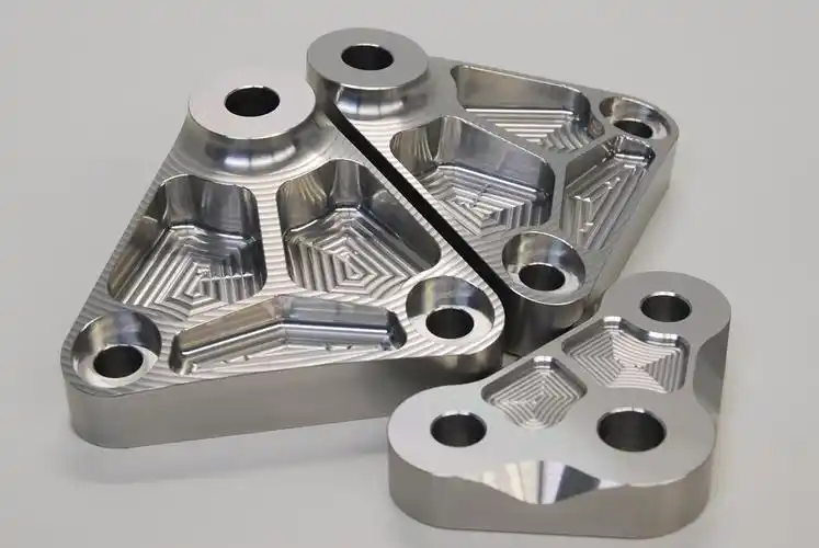
For industrial buyers sourcing complex precision components, 5-axis machining software is the core driver that unlocks the full capability of multi-axis CNC equipment.
how 5-axis machining software improves complex part production?

This guide is written for procurement engineers, maintenance leads and safety teams who need to specify or source machine guards rather than read a safety textbook.
what is the most dangerous part of machines?
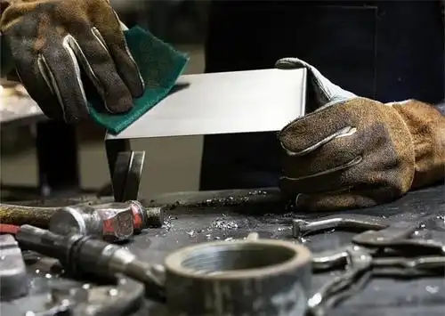
This guide is written for procurement engineers, maintenance leads and safety teams who need to specify or source machine guards rather than read a safety textbook. It covers the hazard points that require protection, the guard types and standards our shop works to, the materials and fabrication options available, the industries they serve, and a selection checklist you can reuse on every guard RFQ.
which parts of a machine must be guarded?